


10
®
3
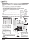
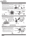
INSTALLING THE W-85 WALL CONTROL
1. Use only the Casablanca W-85 wall control.
2. Do not use any additional control with your Inteli-Touch
3 fan (for example, dimmer, or fan speed control).
3. Do not use more than one fan per wall control.
4. No other light xtures or electrical appliances may be
connected on the circuit controlled by the W-85 wall
control.
If you have multiple Inteli-Touch 3 fans, refer to the section
"Changing Frequency Setting" on page 13.
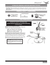
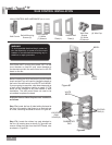
1. Remove the screws and switch plate from the existing switch
box.
2. Remove the screws holding the switch in the switch box.
3. Pull the existing switch from the switch box to expose the
wire connections.
4. Remove the two wires from the switch.
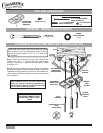
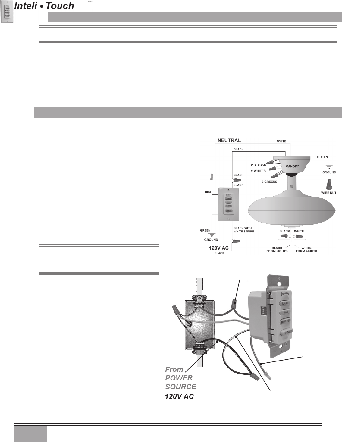
5. Connect the BLACK wire from the POWER SOURCE that
you just removed from the switch to the BLACK/WHITE
STRIP wire on the W-85 wall control. Secure this connection
with a wire nut.
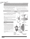
The wall control installs in the same manner as an ordinary light switch, using an existing wall box and wiring. This
controller is designed to signal the fan microcomputer as well as perform normal switching operations. For this
reason the following precautions must be observed:
CAUTION!
Ensure power is turned OFF at the breaker or fuse panel before starting installation.
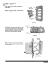
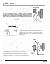
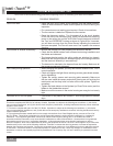
NOTE: The RED wire is not used in this
application, DO NOT remove the crimped cap
from the wire..
BLACK AND WHITE
STRIPED WIRE
W-85
Wall Control
2 BLACK
WIRES
RED WIRE
NOT USED
(FIGURE #2)
(FIGURE #1)
NOTE: W-85 Wall Control should only be installed on Casablanca's Inteli-Touch
®
3 fans with DOWNLIGHTS ONLY.
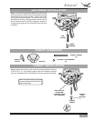
6. Connect the second BLACK wire that you just
removed from the switch to the second BLACK
wire on the located on the back of the W-85 wall
control. Secure this connection with a wire nut.
7. Connect the green ground wire coming from the
back of the W-85 control to the ground wire in
the switch box. Secure the splice with a wire nut.
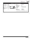
8. Check your work by using the wiring diagrams
as shown in Figures # 1 and #2.
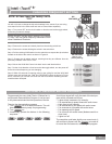
9. Install the W-85 in the wall box with the two
long screws provided.
10. Install the wall plate with the two color-matched
screws.
SINGLE W-85 INSTALLATION
W-85