


2010 Portable Spa
LTR20101000, Rev. C
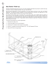
Preparing for Your New Portable Spa
www.calspas.com
5
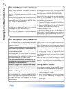
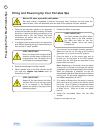
240V GFCI and Wiring Requirements
All 5100 and 6200 control systems are set at the factory to run on the low power setting for 40 amp operation.
This is the default setting. Spa owners can have their installer change this setting so the spa will run on high
power for 50 amp operation.
Warning: Never set a spa to run on high power without installing a properly rated GFCI.
Spa Model GFCI Required Wires Required
4050 control box (5100 and 6200
systems)
Power saver mode -- this is the factory
default setting
One 40 amp GFCI Four #8 AWG copper wires
4050 control box (5100 and 6200
systems)
High power setting -- See
conguration instructions below.
One 50 amp GFCI Four #8 AWG copper wires
9800 control box (except Ultimate
Fitness spas -- see below)
One 50 amp GFCI Four #8 AWG copper wires
5060 control box (6300 system)
Default high power setting -- See
conguration instructions on page 6.
One 60 amp GFCI Four #8 AWG copper wires
Ultimate Fitness Spas:
Fitness spa with 5.5 kW heater:
F854, F1257, FP2400
One 50 amp GFCI Four #8 AWG copper wires
Fitness spa with 11 kW heater:
F1257, F1455, FP1655, FP2500,
FP2400
SEE PAGES 6 AND 7 FOR
INSTALLATION DIAGRAM.
Service 1: One 60 amp
GFCI
Service 1: Four #8 AWG copper wires
Service 2: One 30 amp
GFCI
Service 2: Three #8 AWG copper wires
Fitness Pro 4700 spa
SEE PAGES 6 AND 7 FOR
INSTALLATION DIAGRAM.
Service 1 (swim side):
One 60 amp GFCI
Service 1: Four #8 AWG copper wires
Service 2 (swim side):
One 30 amp GFCI
Service 2: Three #8 AWG copper wires
Service 3 (spa side):
One 40 amp GFCI
Service 3: Four #8 AWG copper wires
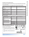
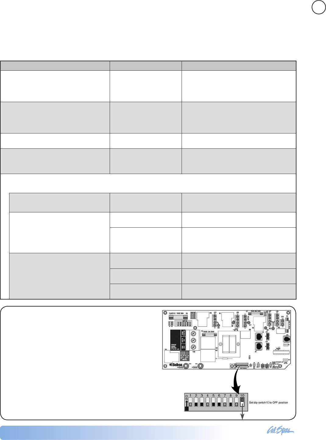
4050 System High Power Conguration
Applies to 5100 and 6200 systems
To operate the spa in high power mode, ensure the
following steps are performed before starting your spa:
When installing the electrical system, use a 50 amp •
GFCI. Follow the GFCI wiring diagram on the next
page.
Have your dealer or installer set dip switch #10 to •
the OFF position on the circuit board as shown at
right.