


CONTROLS
SAFETY INTERLOCK SYSTEM
Your Bush Hog Zero Turn is equipped with a Safety
Interlock System that is designed to help prevent
possible serious injuries. Understanding and main-
taining this system is vital, for safe operation.
To Start Engine:
1. Blades (PTO) must be disengaged.
2. Control levers in neutral (swung out).
3. Parking brake on.
4. Operator in seat.
The Engine Will Kill If:
1. The operator leaves the seat with:
a. The control levers out of neutral (swung in).
b. The blades are engaged.
c. The parking brake is off.
d. All of the above.
2. The park brake is on before the control levers
are in neutral (swung out).
DO NOT OPERATE MOWER IF SAFETY SWITCH-
ES ARE NOT OPERATING PROPERLY.
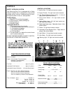
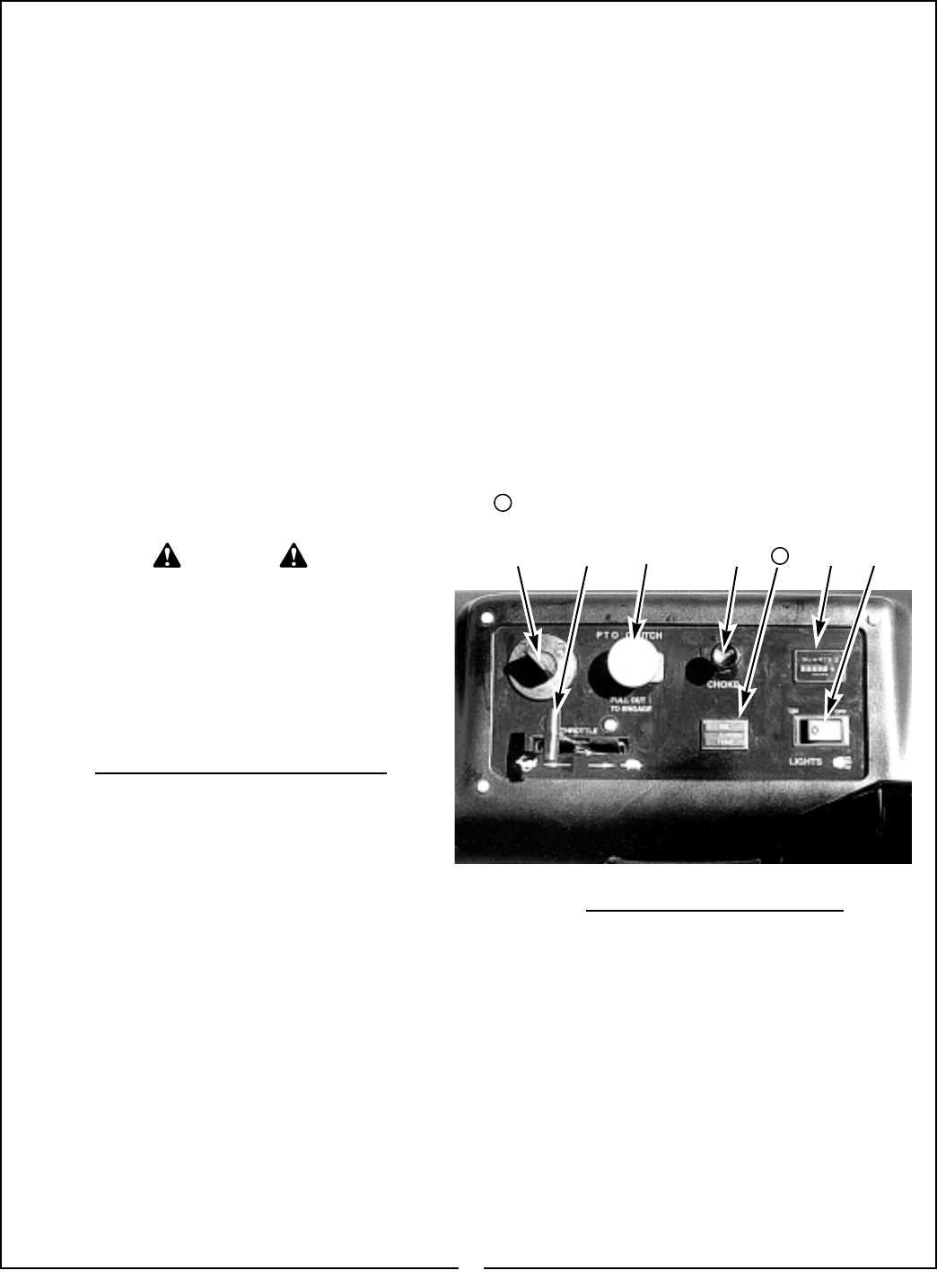
CONTROL LOCATIONS
① Ignition Key - On right hand control console.
② Engine Throttle - On right hand control console.
③ Two Steering/Speed Control Levers - In front of
seat at side. (Not shown below)
④ PTO Clutch Switch - On right hand control
console.
⑤ Parking Brake Lever - On left hand control con-
sole. (Not shown below)
⑥ Blade Height Adjust Lever - Right side of deck. (Not
shown below)
⑦ Choke - On right hand control console.
⑧ Hydrostatic Pump Bypass Valve - Right sides of
pumps. (Not shown below)
Light Switch - On right hand control console.
➉ Hour Meter - On right hand control console.
Warning Light - On right hand control console.
TRACTOR SPECIFICATIONS
Width - All Models . . . . . . . . . . . . . . . . . . . . . . . . . . . . 49”
Height - Kohler Models (Top of seat back) . . . . . . . . . 46”
Kawasaki (Top of seat back) . . . . . . . . . . . . . 46”
All Models with ROPS . . . . . . . . . . . . . . . . . . 72”
Fuel Tank . . . . . . . . . . . . . . . . . . . . . . . Approx. 5 gallons
Hydrostatic Fluid Reservoir . . . . . . . . . Approx. 3 gallons
Hydrostatic Pumps- All Models . . (2) Hydro-Gear pumps
Engine - Zero Turn 18 18 h.p. Kohler Command
Zero Turn 22 22 h.p. Kohler Command
Zero Turn 25 25 h.p. Kohler Command
Zero Turn 22W 22 h.p. Water Cooled Kawasaki
Tires - All Models - Front . . . . . . . . . . . . . . . . 410/350 x 4
Drive . . . . . . . . . Turf 20 - 10.00 x 10
Bar 21 - 11.00 x 10
Knobby 20 - 11.00 x 10
Rear (Single Wheel) . . . 13 - 6.50 x 6
(Dual Wheels) . . . . 13 - 6.50 x 6
DECK SPECIFICATIONS
ITEM D 48-1 D54-1 D 60-1
Cutting width 48” 54” 60”
Cutting Heigh ------------------ 1.00” to 5.00”-------------
Blades 17” 19” 21”
Overall width
including chute 63-1/2” 66-1/2” 73-1/2”
Material thickness - skirt -------------7 GA.---------------
- deck -----------10 GA.--------------
Reinforcement plate ------------------7 GA.---------------
Spindle bearings ----------------------25 mm--------------
①
② ④
⑦
8
WARNING
DO NOT OPERATE MACHINE UNLESS
INTERLOCK SYSTEM FUNCTIONS PROP-
ERLY. FAILURE TO HEED THIS WARNING
MAY RESULT IN SERIOUS INJURY, DEATH
OR EQUIPMENT DAMAGE.
⑨
⑨
11
11
➉