


ASSEMBLY:
BUSH HOG BACKHOE AND A NON BUSH HOG
LOADER - OR - BUSH HOG BACKHOE AND
LOADER USING PTO PUMP KIT OPTION
IMPORTANT: Improper hydraulic hook-up can cause
serious damage to backhoe control valve or other
hydraulic components.
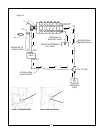
The following instructions are to be used to connect the
backhoe valve in line with a front end loader valve that
is not a Bush Hog loader valve. When connecting the
Bush Hog backhoe valve to a loader valve other than
one obtained from Bush Hog, the input pressure line
from the tractor will be connected to the backhoe valve
first. In order to properly plumb the system, the back-
hoe valve will require converting to a power beyond
valve. The power beyond pressue line from the back-
hoe valve will be connected to the input pressure port
of the loader valve. The power beyond kit for the back-
hoe being assembled must be ordered as a separate
item from Bush Hog.
Assembly
IMPORTANT: Improper hydraulic hook-up can
cause serious damage to backhoe control valve
or other hydraulic components.
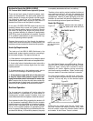
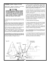
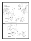
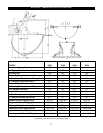
1. Install power beyond sleeve (1) into valve cavity,
as shown in Figure 24 (Page 33), making sure that
O-rings and back-up ring on sleeve are positioned
properly and are not pinched or damaged.
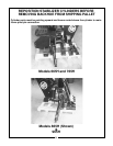
2. 665H and 765H - Assemble 90 degree O-ring
adapter union (2) to power beyond sleeve (1) and
direct fitting down through notch in Right Hand foot
pad.
865H & 965H - Assemble straight O-ring adapter
union (3) to power beyond sleeve (1). Install 90
degree pipe threaded adapter union (2) into adapter
union (3).
3. Assemble hydraulic hose (supplied by customer)
to adapter union (2) as shown in Figure 24. Hose
should have same pressure rating as original pres-
sure hose to loader or other accessory valve.
4. Install hose sleeve (4) onto hose assembled in
step 3. Position hose sleeve to completely
cover
adapter union (2) and secure with plastic tie (8) as
shown in Figure 24.
Hose sleeve (4) is installed to help protect the
backhoe operator from escaping fluid under
pressure. If it becomes damaged or lost, replace
hose sleeve (4) and plastic ties (8) immediately.
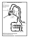
5. Assemble hydraulic hose (see step 3) from back-
hoe power beyond port to loader or accessory valve
inlet port using fittings (supplied by customer) as
needed. Refer to Figure 24.
6. Complete assembly of backhoe “pressure” and
“return” hoses as shown in Figure 24 using hoses
and tee fitting (supplied by customer).
7. Complete assembly of loader “return” hose to tee
fitting as shown.
8. Replace shroud using hardware removed in step
1 of “Backhoe Preparation” section.
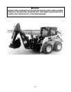
CAUTION
33