


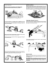

3. Remove plastic bag containing bucket pins from
backhoe. Attach bucket (D) to dipperstick using one
pin, two bolts, nuts, lockwashers, pin retainers and
washers as necessary.
4. Attach bucket link (E) to bucket, using same hard-
ware as listed for step #3.
5. Attach hoist to backhoe to prevent tipping. Remove
all remaining strapping and attach stabilizers (F) to
mainframe (G) using pins and hardware assembled to
backhoe.
21
6. Attach stabilizer cylinders (H) to stabilizers using
pins and hardware assembled to stabilizers.
7. Using caution to prevent tipping, raise mainframe
with hoist to a height of approximately 11” for 862H
and 13” for 962H and remove skid. Block mainframe
(G) and swing frame (I) securely.
8. Follow the Attaching Kit Assembly Instructions to
mount the backhoe to the tractor. Check the installa-
tion carefully and make sure that all members are cor-
rectly installed and securely fastened.
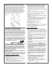
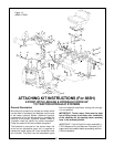
Assembly:(665H & 765H) - Figure 12
(See “General” note, page 20)
IMPORTANT: Tighten all hardware to torque
requirements specified in torque chart.
DO NOT cut any strapping that fastens the back-
hoe mainframe and swing frame to the skid at
this time.
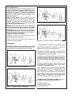
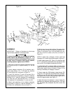
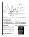
1. Remove the stabilizer assemblies and any miscella-
neous items which have been fastened to skid and
arrange conveniently. Reposition stabilizer cylinders from
their shipping configuration, by assembling them into the
mainframe, using the hardware provided. Be sure cylinder
ports are pointed upward and hoses are routed above the
cylinder to mainframe pivot pin connection. Refer to page 36.
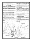
2. Support Boom (A) and Dipperstick (B) with hoist
and remove Boom transport lock pin. Lower Boom
and manually extend Dipperstick until it rests on the
ground. Move control handle to “Boom Down” position
as required to aid movement.
Be sure hoist being used is suitable, has suffi-
cient capacity and is in the proper position. Do
not allow anyone under a backhoe member sup-
ported by hoist.
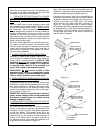
3. Remove plastic bag containing bucket pins from
backhoe. Attach Bucket (D) to Dipperstick using one
pin, two bolts, locknuts, pin retainers, and washers as
needed to take up gap under pin retainers.
4. Attach Bucket Link (E) to Bucket, using same
hardware as listed for step #3.
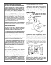
5. Reposition hoist on backhoe to prevent tipping and
raise Mainframe slightly. Remove all remaining strap-
ping and crate base. Using caution to prevent tipping,
raise Mainframe (G) approximately 10” and block
Mainframe and Swing Frame securely.
6. Attach Stabilizers (F) to Mainframe (G) using pins
and hardware assembled to Stabilizers (F).
7. Attach Stabilizer Cylinders (H) to stabilizers (F)
using pins and hardware assembled to Stabilizers (F).
8. Follow the Attaching Kit Assembly Instructions to
mount the backhoe to the tractor. Check the installa-
tion carefully and make sure that all members are cor-
rectly installed and securely fastened.
CAUTION
CAUTION
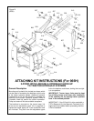
ATTACHING KIT INSTRUCTIONS (For 665H & 765H)
3-POINT HITCH LINKAGE & HYDRAULIC HOOK-UP
TO TRACTOR HYDRAULIC SYSTEMS
General Description
Mounting and hydraulics kits include two hoses which
can be used to connect the backhoe to the tractor
hydraulic system. Additional hydraulic components or
kits will be required to complete the hook-up to the
tractor hydraulic system. Refer to the Hydraulic Hook-
up section for further information. Pumps and reser-
voir kits are available as options.
The backhoe is mounted on the tractor lower link
arms and an adjustable upper link is supplied to
replace the tractor upper link. A set of stabilizer arms
is included. They bolt from the adjustable upper link to
the backhoe mainframe, locking the hoe rigidly in one
position.
IMPORTANT: Tractor lower links must be kept
free of lifting forces at all times after installation
of the attaching kit, by keeping tractor quadrant
lever in the lowered position.
IMPORTANT: If the 3-Point Kit is to be used with a
PTO & Reservoir Kit, the Reservoir Tank and it’s fit-
tings should be installed before proceeding with the
3-Point installation.