


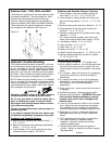

Figure 15
4
38
35
37
5
3
23
15
25
8
7
12 11 9
10 13
26 24
25
22
16 17
20 19
18
21
31
25
25
26
24
34
33 22
24
26 25
2
30
32
25
28
27
29
14
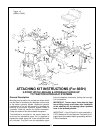
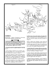
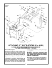
ASSEMBLY
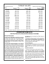
IMPORTANT: Tighten all hardware to the torque
requirements specified in the torque chart.
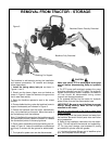
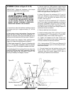
To prevent bodily injury, do not operate backhoe
unless Lower Link Weldments ( Figure 15 - 1, 2)
are properly installed and adjusted. Failure to do
so may result in backhoe being thrust upward,
crushing operator against cab or ROPS.
1. Use hoist to raise the backhoe mainframe so that
the boom pivot pin is approximately 16” off the
ground.
2. Attach adapter weldment (3) to backhoe main-
frame using twelve 1/2 x 7-1/2” bolts (4), washers
(5), and locknuts (6), as shown in Figure 15.
3. Install RH foot pad (7) and LH foot pad (8) to
adapter weldment (3) as shown in Figure 15. Use four
carriage 5/16 x 1” bolts (9), washers (10), lockwashers
(11), and nuts (12). Also use two 5/16 x 1-1/4” bolts
(13), washers (10), lockwashers (11), and nuts (12).
4. Attach seat assembly (14) to adapter weldment
(3) as shown in Figure 15. Use four carriage 1/2 x 1-
3/4” bolts (15), lockwashers (16), and nuts (17).
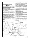
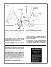
5. Back tractor close to the backhoe. Connect tractor
lower link arms to lower link mounts at position “C”,
Figure 16, using two L-pins (18), two cotter pins (19),
and two wire form cotter pins (20) as shown in
Figure 15.
NOTE: If tractor has a Category II hitch, install two
bushings (21) in lower link arms as shown in Figure 15.
6. Attach upper braces (22), Figure 15 to backhoe with
3/4 x 7-1/2” bolt (23), lockwasher (24), flat washers (25)
and nut (26). Do not tighten hardware at this time.
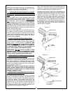
7. Install bushing (27) or bushing (28) in the hole of the
upper bar (29) that most closely matches the diameter
of the tractor upper link pin, as shown in Figure 15. No
bushing is necessary for Category II tractors.
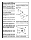
8. Secure upper bar (29) between upper braces (22)
using 3/4 x 4-1/2” bolt (30), flat washers (25), lockwash-
er (24) and nut (26). Use hoist to raise or lower back-
hoe slightly until a hole in the upper bar aligns with a
hole in the upper braces. See Figure 15.
9. Attach RH lower link weldment (1) and LH lower link
weldment (2) to backhoe mainframe using 3/4 x 2-1/4” bolt
(31), flat washer (25), lockwasher (24), and nut (26). See
Figure 15.
WARNING
24
1
6
36
35