


Tooth Replacement
The bucket tooth points are self-sharpening and will
require little attention; however, these points on the
bucket shanks can be replaced when they become
badly worn or broken. If a tooth shank breaks off,
becomes damaged or lost so that it cannot hold a
tooth point, a new shank should be welded to the
bucket in its place.
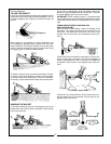
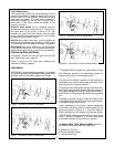
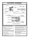
Weld-On tooth points can be removed from the
welded tooth shank by hammering at “A” (Figure 5) on
the tooth point or by driving a chisel at “B”, just
between the tooth point box section and the tooth
shank. Install the new point and anchor it to the shank
by peening at the location shown.
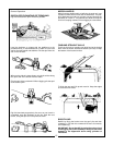
Bolt-On tooth points, when worn, can be replaced by
removing the hardware that connects it to the cutting
lip. Install new tooth and replace hardware if necessary.
Roll-Pinned tooth points, when worn, can be replaced
by driving out the roll pin with a hammer and punch.
Install the new tooth using a new roll pin and hammer.
Tightening Nuts and Bolts
Periodically, check to be sure all bolts and nuts are
tight. See torque chart, page 28 .
Check all pivot pins for cotter pins, washers and
retainers; if missing, replace.
Lubrication
IMPORTANT: Avoid excessive greasing. Dirt collects
on exposed grrease and increases wear greatly. After
greasing, wipe off excessive grease from fittings.
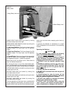
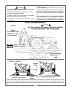
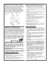
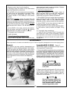
Figure 6 - Lubrication Points for Model 665H
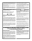
Figure 7 - Lubrication Points for Model 765H
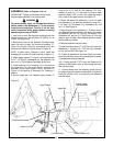
Figure 8 - Lubrication Points for Model 865H
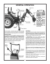
Economical and efficient operation of the backhoe is
dependent upon regular and proper lubrication of all
moving parts with a quality lubricant.
All parts provided with grease fittings should be lubri-
cated with a good quality chassis lube type grease. If
any grease fittings are missing, replace them immedi-
ately. Clean all fittings thoroughly before using grease
gun.
Lubricate all grease fittings at least twice daily, once
at the beginning of operation and again approximate-
ly halfway through the work day.
Lower stabilizers to the ground, extend dipperstick
and bucket and lower boom so bucket rests on the
ground as shown in Figures 6, 7, 8 and 8A. Refer to
these illustrations for the location of all grease fittings.
*IMPORTANT: Before greasing boom to swing frame
pivot (*) shown in Figures 6, 7, 8 & 8A, raise boom
and install transport lock pin shown in Figure 1.
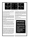
On Models 665H, 765H, 865H and 965H the follow-
ing locations should be oiled with SAE30 oil:
A. Stabilizer Pivot Pins
B. Control Handle Linkage
C. Seat Bracket Pivot
15
①
①
①
①
①
①
①
①
①
①
①
①
①
③
③
①
①
①
①
①
①
①
①
①
①
①
①
①
①
①
①
①
①
①
①
①
①
①
①
①
①
①
③
②
*
*
*
➀
**
➀
➀
➀
➀
➀
➀
➀
➀
➀
➀
➀
**
➀
➀*
➂
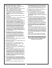
Figure 8A - Lubrication Points for Model 965H
** On Model 965H the Upper and Lower Swing Frame
Pivot Bearings located in the Mainframe should be
replaced every 300 to 400 operating hours.