


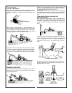
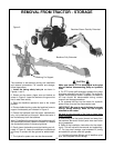

1. Remove control valve from the backhoe.
2. Thoroughly clean the exterior of the valve before
beginning disassembly procedures.
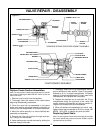
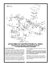
3. At the BACK of the valve remove all bonnet assem-
bly parts which are connected to the spool. Keep
parts in the order of disassembly. See Figure 11 for
the parts involved in the make-up of the bonnet
assembly.
IMPORTANT: DO
NOT remove the spool from the
valve. The seals can be replaced externally. Prevent
spools from turning or moving by inserting a screw dri-
ver through the clevis slot, or by running a rod through
the pin hole and using the rod as a handle. DO NOT
hold the spool with a wrench. This will destroy the fin-
ish.
4. At the BACK of the valve, remove seal retainer,
back-up washer, and spool O-ring seal, or
retaining
sleeve,bonnet O-ring seal and spool U-cup seal.
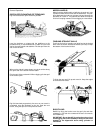
5. Thoroughly clean counterbores.
6. Install new seals:
A. Spring-Centered Bonnet
Assembly Only:
Lightly oil new O-ring seal. Slide O-ring seal over
valve spool and insert in seal counterbore. Replace
back-up washer and seal retainer.
B. Float Bonnet Assembly Only:
Replace retaining sleeve on valve spool. Lightly oil
new U-cup seal. Slide U-cup seal over valve spool
being careful to orient seal as shown in Figure 11.
Install new O-ring seal in bonnet counterbore.
7. At the BACK of the valve replace bonnet assembly
parts, reversing the order in which they were disas-
sembled in step 3. Use 12 ft. lbs. torque to tighten
assembly screw on spring centered bonnet assembly.
8. At the FRONT of the valve remove all parts con-
nected to the spool (handle, linkage, etc.).
9. At the FRONT of the valve remove seal plate retain-
er, seal retainer, back-up washer and spool O-ring
seal.
10. Thoroughly clean counterbore.
11. Lightly oil new O-ring seal. Slide O-ring seal over
valve spool and insert in seal counterbore. Replace
back-up washer, seal retainer, and seal plate retainer.
12. Reattach all parts connected to the spool (handle,
linkage, etc.).
20
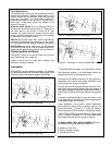
ASSEMBLY
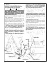
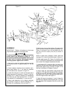
Basic components for all models can be identified in Figure 12. Refer to Page 38 for photographs of units on their shipping pallets.
General:
The backhoe has been partially disassembled and
strapped to a skid for shipping purposes. Initial installa-
tion on the tractor will require a hoist or other device
capable of safely lifting the entire backhoe from the skid.
After the initial installation is complete, the backhoe can
serve as its own erecting hoist, by lowering stabilizers
and bucket to the ground. Additional lifting devices will
not be required for normal removal and reattaching.
Assembly(865H & 965H) - Figure 12
IMPORTANT: Tighten all hardware to torque require-
ments specified in torque chart.
1. Remove the stabilizer assemblies and any miscellaneous
items which have been fastened to the skid and arrange
conveniently. Reposition Stabilizer Cylinders from their ship-
ping configuration, by assembling them into the mainframe,
using the hardware provided. Be sure cylinder ports are
pointed upward and hoses are routed above the cylinder to
mainframe pivot pin connection. Refer to page 38.
Figure 12
CAUTION
DO NOT cut any strapping that
fastens the backhoe mainframe
and swing frame to the skid base
at this time.
CAUTION
Be sure hoist being used is suit-
able, has sufficient capacity and
is in the proper position. Do not
allow anyone under a backhoe
member supported by hoist.
C
B
E
D
A
I
G
H
F
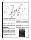
2. Support boom(A) and dipperstick (B) with hoist and
remove boom transport lock pin. Lower boom and
manually extend dipperstick until it rests on ground.
Move control handle to “BOOM DOWN” position as
required to aid movement.