


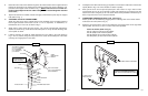


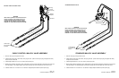


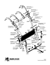


A-Attach to metal line on mainframe that is connected to the Base End of the lift cylinder (color code
blue) using a 68” hydraulic hose and adapter provided in kit.
B-Attach to control valve at port that controls Base End of the lift cylinder, (color code blue).
C-Attach to metal line on mainframe that is connected to the Rod End of the lift cylinder (color code
red) using a 68” hydraulic hose and adapter provided in kit.
D-Attach to control valve at port that controls Rod End of the lift cylinder, (color code red).
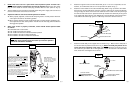
E-Attach one side of TEE to metal line on mainframe that is connected to the Base End of the bucket
cylinder (color code green) using a 68” hydraulic hose and adapter provided in kit.
Attach the additional side of TEE to the control valve port that controls the Base End of the bucket
cylinder.
F- Attach one side of TEE to metal line on mainframe that is connected to the Rod End of the bucket
cylinder (color code yellow) using a 68” hydraulic hose and adapter provided in kit.
Attach the additional side of TEE to the control valve port that controls the Rod End of the bucket
cylinder.
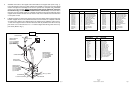
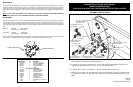
Note: Tie the (4) 68” hoses routed to the metal lines from the self leveling valve together with the ties
provided in the kit. Use one of the ties to secure the hose bundle to the inside of the pedestal by loop-
ing the tie through one of the square holes toward the inside rear of the pedestal and around the hose
bundle.
A
B
C
D
E
F
A
B
C
D
E
F
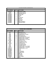
68’’Hoses in Kit
(4) Unions 3/4” JIC male
To Rod End Bucket (Yellow)
To Rod End Lift (Red)
To Base End Bucket (Green)
To Base End Lift (Blue)
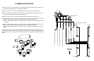
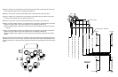
Rod End
Rod End
Rod End
Rod End
Base
End
Base
End
Base
End
Base
End
R.H. Lift Cylinder
R.H. Bucket Cylinder
L.H. Bucket Cylinder
L.H. Lift Cylinder
FRONT
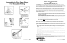
D - To control valve port for rod end lift.
B - To control valve port for base end lift.
F - To control valve port for rod end bucket.
E - To control valve port for base end bucket.