


50051690 SELF LEVELING VALVE BUNDLE
MOUNTING INSTRUCTIONS
BUSH HOG 3545, 4045, 5045 & 6045 MID MOUNT FRONT END LOADERS
~ ASSEMBLY INSTRUCTIONS ~
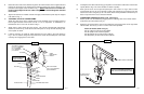
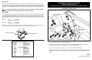
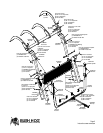
1. Attach self leveling valve to the right hand pedestal using the (2) 5/16”- 2 1/2” Gr. 5 capscrews,
5/16” lockwashers and 5/16” hex nuts provided in kit.
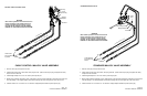
2. In ports A, C, & D install a 7/8” ORB male - 3/4” JIC male straight thread adapter in each port. To
each straight adapter attach a 3/4” JIC female - 3/4” JIC male 90° elbow.
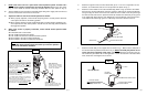
3. In ports B, E & F install a 7/8” ORB male - 3/4” JIC male 90° elbow into each port.
4. Install a 3/4” JIC female - 3/4” JIC male TEE to each of the 90° elbows in ports E & F with the single
leg pointing out. Install a 3/4” JIC female - 3/4” JIC male 90° elbow to each outward pointing leg of
TEE’s.
05/03/06
62-06
Instruction Sheet 50051610
A
B
C
D
E
F
(2) 5/16” x 2 1/2” capscrew Gr.5
(2) 5/16” lockwasher
(2) 5/16” hex nut
7/8” ORB male to 3/4” JIC
male 90° elbow
7/8” ORB male to 3/4”
JIC male 90° elbow
7/8” ORB male to
3/4” JIC male adapter
3/4” JIC female to 3/4”
JIC male 90° elbow
3/4” JIC female to 3/4”
JIC male 90° elbow
3/4” JIC female to 3/4”
JIC male TEE
DESCRIPTION
The hydraulic self-leveling option is designed to be incorporated into Bush Hog’s standard loader hydraulic circuit. A dual self-
level valve controls flow throughout the system so as to maintain a nearly constant position of the loader attachment relative
to the ground. The valve performs this function in both the raising and lowering mode. The bucket (or other attachment) may
be operated at any time, independent of the self-level valve, giving the operator the ability to reposition it throughout the work
cycle.
NOTE
: IF THE LOADER ATTACHMENT ROLLS COMPLETELY BACK WHILE LOWERING THE BOOM, DOWNWARD
MOTION WILL CEASE; ROLL THE ATTACHMENT FORWARD TO CONTINUE LOWERING.
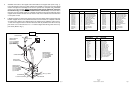
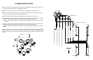
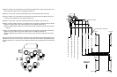
ADJUSTMENT
Since the same self-level valve is used on different Bush Hog loaders, adjustment of the valve may be required when installed
on one particular loader or the other to obtain a preferred performance. There are two separate adjustment screws, one for the
raising mode and one for the lowering mode. Remove the dust cap to access the adjustment screw and loosen the jam nut
prior to adjusting. Adjustments should be made in 1/4 turn increments to achieve the desired motion according to the following
logic:
RAISING: Clockwise - More Rollback
Counterclockwise - More Dump
LOWERING: Clockwise - More Dump
Counterclockwise - More Rollback
Being a “needle valve” type adjustment, a point is reached when backing the adjustment screw out further (counterclockwise)
has no effect. The maximum effective range of adjustment in this situation is approximately 2-3 turns.
Raising Adjustment
Lowering Adjustment
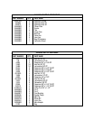
50051690 SELF LEVEL VALVE BUNDLE
PART NUMBER QTY. PART NAME
25H50700 4 HYDRAULIC HOSE 68”
25H49136 1 DUAL SELF LEVEL VALVE
50027314 1 BAG OF HARDWARE
50051610 1 INSTRUCTION SHEET
68822 1 CRATE
50027314 BAG OF HARDWARE
25H47571 5 NYLON CABLE TIES
25H43832 3 HYDRAULIC ADAPTER
25H43235 2 HYDRAULIC TEE
25H40576 5 HYDRAULIC ELBOW
25H40475 3 HYDRAULIC ELBOW
25H40043 4 HYDRAULIC ADAPTER
15528 2 HEX NUT 5/16’’
15808 2 LOCKWASHER 5/16’’
20504 2 CAPSCREW 5/16” X 2-1/2” GR.5
51260 1 BAG
3/4” JIC female to 3/4”
JIC male 90° elbow
7/8” ORB male to 3/4” JIC
male 90° elbow
3/4” JIC female to 3/4”
JIC male TEE