


Page 4
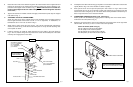
8. Rotate the valve ends of the cables through the notch at the bottom of the support tube and
through the large hole in the support mount and floor board of the tractor. Attach the sup-
port tube to the support mount as shown in Fig. 1. (NOTE
: Take care to not cut cable cov-
ering on sharp edges and be sure cable routing will not cause binding when attached
to the valve).
9. Tighten all fasteners for handle controls and apply control decal to plate atop the support
tube (Refer to Fig. 1).
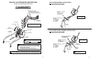
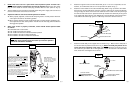
10. ATTACHING VALVE TO LOADER FRAME:
Attach the valve mount to the outside surface of the pedestal on the mounting bracket of
load on right hand side of the tractor. Use the
1/2” x 2 1/4” capscrews, 1/2” flatwashers, 1/2”
lockwashers and
1/2” hex nuts as shown in Fig. 4.
11. Attach valve to valve mount using the (4) m8 x 1.25 x 20 Gr. 8.8 capscrews and m8 lock-
washers as shown in Fig. 4. Be sure that the work ports are on top and the attaching ends
of the spools are down.
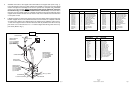
12. It will be necessary to install the cable attaching kit on the cable in the order shown in
Fig. 4. The nut, washer, flange and cap must be ran across the threaded part of the cable
until they are hanging loose on the cable.
Fig. 4
VALVE MOUNT
VALVE MOUNT TO PEDESTAL :
(2) 1/2” X 2 1/4
” CAPSCREWS
(2)
1/2” FLATWASHERS
(2)
1/2” LOCKWASHERS
(2)
1/2” HEX NUTS
SPOOL END
LIFT CIRCUIT CABLE
LOADER
MOUNT BRACKET
PEDESTAL
VALVE TO VALVE MOUNT :
(4) m8 x 1.25 x 20 CAPSCREWS
(4) m8 LOCKWASHERS
“O” RING
PIN
JOINT
CAP
FLANGE
SOCKET HEAD SCREW
WASHER
ATTACHMENT CIRCUIT CABLE
VALVE
Page 5
13. Install joint to the cable end and snug up the jamb nut. Connect the cable to the control valve
spools (Refer to Fig. 3 for correct location of cables to spools).
14. Place joint in slot on end of spool and place pin in hole. Place “O” ring in inset of valve
around spool and run cap up on threads of cable end. Pull flange up around the cap and
attach to the valve using the (2) m5 x 20 socket head screws provided. Pull washer up to
base of cap and run the nut to contact the washer.
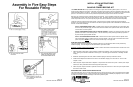
15. CONNECTING HYDRAULICS (Refer to Fig. 5 and Fig. 6):
Attach (4) 68” hose assemblies by plugging into the matching color on the female halves
mounted on the valve (Refer to Fig. 5).
16. Attach the (4) hoses from the valve to the metal lines on the boom frame on the right hand
side of loader. Use the (4)
3/4
” JIC x 3/4” JIC male unions provided.
Attach as follows: (Refer to Fig. 5).
Port A1 (Blue) to head end of lift cylinder.
Port B1 (Red) to rod end of lift cylinder.
Port A2 (Yellow) to rod end of bucket cylinder.
Port B2 (Green) to head end of bucket cylinder.
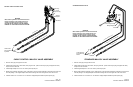
Fig. 5
(RED) - PORT B1 TO ROD END LIFT CYLINDER.
(BLUE) - PORT A1 TO HEAD END LIFT CYLINDER.
(YELLOW) - PORT A2 TO ROD END BUCKET CYLINDER.
(GREEN) - PORT B2 TO HEAD END BUCKET CYLINDER.
RED
BLUE
YELLOW
GREEN
TO METAL LINES ON LOADER FRAME.
TO SUPPLY PORTS AT
REAR OF TRACTOR.
PRESSURE
RETURN
Hoses and Quick
Disconnect Fittings Not
Shown for Clarity!
JAMB NUT
HEX NUT