


Page 6
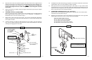
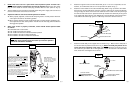
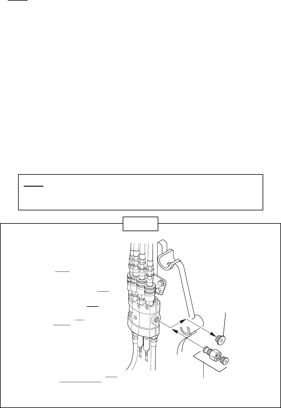
17. NOTE: This valve is set for a open center tractor hydraulic system. If tractor has a
closed center system a closed center plug must be installed. Remove the open center
plug in valve. Install the closed center plug furnished with the valve (Refer to Fig. 6).
18. Tighten all fittings and connections and install proper fitting to the supply and return lines at
the rear of the tractor and connect to the tractor.
19. Adjust the cables so the control handle operates as follows:
z When properly adjusted, control handle will spring back to neutral position whenever
valve spool is moved into the working position.
z When properly adjusted, control handle will be able to pushed forward, positioning the
valve spool into the float detent position. Handle must be manually pulled rearward to
disengage float position.
20. When valve circuit is properly connected, control handle should operate loader
as follows:
z Pull handle back to raise loader.
z Push handle forward to lower loader.
z Push handle full forward to activate float detent position.
z Move handle to the right to dump attachment.
z Move handle to the left to roll back the attachment.
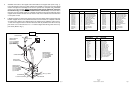
Fig. 6
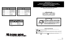
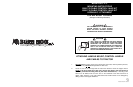
NOTES:
1. WHEN ATTACHING A LOADER VALVE TO THE REAR
REMOTES OF THE TRACTOR, A POWER BEYOND IS
NOT REQUIRED. A POWER BEYOND KIT MUST
BE
USED WHEN ATTACHING A LOADER VALVE TO A
HYDRAULIC SOURCE OTHER THAN THE REAR
REMOTES OF A TRACTOR HAVING AN OPEN CENTER
HYDRAULIC SYSTEM.
2. A POWER BEYOND KIT IS NOT
REQUIRED ON
TRACTORS WITH A CLOSED
CENTER HYDRAULIC
SYSTEM. THE LOADER VALVE MAY BE ATTACHED TO
THE TRACTOR AT THE REAR REMOTES OR, AT
ANOTHER HYDRAULIC SOURCE RECOMMENDED BY
THE TRACTOR MANUFACTURER.
3. IF POWER BEYOND SYSTEM IS USED, REFER TO
BASIC POWER BEYOND PLUMBING INSTRUCTIONS
FURNISHED WITH POWER BEYOND KIT.
4. IF THE TRACTOR HAS A PRESSURE FLOW COM-
PENSATED SYSTEM (PFC) - THE LOADER VALVE MUST
BE CONNECTED TO THE TRACT
OR REMOTES
.
NOTE: Cotaminant’s in hydraulic oil can cause valve spools to stick.
BE ALERT when operating loader and follow your tractors operators
manual oil maintenance schedule.
OPEN CENTER PLUG
REMOVE FOR TRACTORS WITH
CLOSED CENTER SYSTEMS
AND REPLACE WITH CLOSED
CENTER PLUG ASSEMBLY.
CLOSED CENTER PLUG
REPLACE THE OPEN CENTER PLUG
WITH THIS ASSEMBLY FOR TRACTORS
WITH CLOSED CENTER SYSTEMS.
Page 3
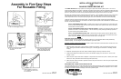
5. Attach the support mount to the floor board with (4) 3/8” x 2 3/4” Gr. 5 capscrews, 3/8” flat-
washers,
3/8” lockwashers and 3/8” hex nuts provide in kit (Refer to Fig. 1).
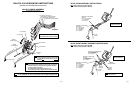
6. Attach the control cables to the control handle body (Refer to Fig. 2). Remove the rubber
boot from the control handle body. Insert the end of the cable into the control handle body
enough to align the clevis on the end of the cable tab on the handle. Insert the pin through
the clevis and tab and secure in place with the E-clip. Position the cable body so the groove
in the cable body aligns with the cross drilled hole in the handle body. Insert metric bolt in
cross drilled hole and through groove in cable body and secure with the metric nut.
Fig. 2
BOOT
CONTROL CABLE
GROOVE IN CONTROL CABLE
HOUSING
E-CLIP
PIN
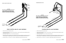
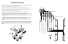
7. Attach the handle body to the support tube as shown in Fig. 1. Make sure the solid post in
the control handle is positioned as shown in Fig. 3. (NOTE
: The solid post position is crit-
ical for the correct operation of this valve). Install the rubber boot. The knob on the con-
trol handle must be rotated 180
0
for this application. Loosen the setscrew in the base offline
knob, rotate 180
0
and retighten the set screw.
25H41276
Fig. 3
VALVE
SOLID POST LOCATION
(NOTE
: SOLID POST LOCATION IS
CRITICAL FOR CORRECT VALVE
OPERATION).
ATTACHMENT CIRCUIT CONTROL CABLE
TOP VIEW OF HANDLE HOUSING
WITH BOOT REMOVED.
FRONT OF TRACTOR
LIFT CIRCUIT
CONTROL CABLE