


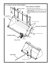
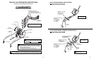


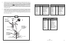
3. Assemble the mount to the support tube and handle to the support tube (refer to Fig. 1).
Leave all fasteners snug but not tight. position the assembly on the area of the floor board
chosen and adjust the assembly to be sure the operator has complete and comfortable
access to the control handle. (NOTE
: The support mount may be rotated 180
0
from posi-
tion shown in Fig. 1 if necessary for better access to the controls). If the tractor has a
floor matt, use the support mount as a template and mark the area around the base of the
support mount where it contacts the matt. Cut the matt on the marked area and remove the
cut out piece of matt.
4. It will be necessary to remove the support mount from the support tube to perform this step.
Position support mount on the cab floor board and use the mount as a template. Drill four
3/8” holes in line with the four slotted holes in the support mount. Mark the center of the 1
1/4” hole in the support mount on the floor board as close as possible to the hole in the sup-
port mount. Use a hole saw and cut a 1
1/4” hole that aligns with the large hole in the sup
port mount (Refer to Fig. 1).
25H41276
Fig. 1
CONTROL HANDLE
DECAL
SET SCREW
CONTROL HANDLE TO
SUPPORT TUBE :
(2)
5/16” X 5 CAPSCREWS
(2)
5/16” FLATWASHERS
(2)
5/16” LOCKWASHERS
(2)
5/16” HEX NUTS
CONTROL CABLES
NOTCH AT BASE
OF SUPPORT TUBE
SUPPORT TUBE TO
SUPPORT MOUNT :
(2) 3/8” X 2 3/4” CAPSCREWS
(2)
3/8” FLATWASHERS
(2)
3/8” LOCKWASHERS
(2)
3/8” HEX NUTS
SUPPORT MOUNT
1
1/4” HOLE IN FLOOR BOARD
SUPPORT MOUNT TO
CAB FLOOR BOARD :
(4)
3/8” X 2 3/4” CAPSCREWS
(4)
3/8” FLATWASHERS
(4)
3/8” LOCKWASHERS
(4) 3/8” HEX NUTS
DRILL (4) 3/8” HOLES
FLOOR BOARD
Page 2
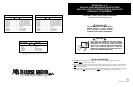
50051730 CABLE CONTROL VALVE KIT
PART NUMBER QTY. PART NAME
50051669........................ 1..............68” Hose Assembly (Green)
50051670........................ 1..............68” Hose Assembly (Red)
50051671........................ 1..............68” Hose Assembly (Yellow)
50051672........................ 1..............68” Hose Assembly (Blue)
50041056........................ 2..............Hydraulic Hose (120”)
50041068........................ 1..............Cable Control Valve Ass’y
50020851........................ 1..............Control Handle
50020540........................ 2..............Control Cable (78”)
50026999........................ 2..............Cable Connector Kit
50027394........................ 1..............Support Weldment
50027391........................ 1..............Support Tube Weldment
50027388........................ 1..............Valve Mount
50051651........................ 1..............Instruction Sheet
50027390........................ 1..............Bag Of Hardware
68822.............................. 1..............Crate
50051729 CABLE CONTROL VALVE KIT
PART NUMBER QTY. PART NAME
50051669........................ 1..............68” Hose Assembly (Green)
50051670........................ 1..............68” Hose Assembly (Red)
50051671........................ 1..............68” Hose Assembly (Yellow)
50051672........................ 1..............68” Hose Assembly (Blue)
50041057........................ 2..............Hydraulic Hose (156”)
50041068........................ 1..............Cable Control Valve Ass’y
50020851........................ 1..............Control Handle
50020540........................ 2..............Control Cable (78”)
50026999........................ 2..............Cable Connector Kit
50027394........................ 1..............Support Weldment
50027391........................ 1..............Support Tube Weldment
50027388........................ 1..............Valve Mount
50051651........................ 1..............Instruction Sheet
50027390........................ 1..............Bag Of Hardware
68822.............................. 1..............Crate
50027390 BAG OF HARDWARE
PART NUMBER QTY. PART NAME
25H47571........................5..............Cable Tie
08151600........................ 2..............Hexnut 1/2” ZP
15528.............................. 2..............Hexnut 5/16” ZP
08151200........................ 6..............Hexnut 3/8” ZP
15806.............................. 2..............Lockwasher 1/2” ZP
15812.............................. 6..............Lockwasher 3/8” ZP
15808.............................. 6..............Lockwasher 5/16” ZP
44311.............................. 4..............Lockwasher M8 ZP
15915.............................. 6..............Flatwasher 3/8” ZP
15916.............................. 1..............Flatwasher 1/2” ZP
15907.............................. 2..............Flatwasher 5/16” ZP
44098.............................. 6..............HHCS 3/8” x 2 3/4” G5 ZP
44582.............................. 2..............HHCS 5/16” x 5” G5 ZP
44315.............................. 4..............HHCS M8 x1.25”x20” G8.8 ZP
15080.............................. 2..............HHCS 1/2” x 2 1/4” G5 ZP
25H43832....................... 2..............Straight Thread Adaptor
25H41276....................... 1..............Valve Control Decal
51260.............................. 1..............Bag
Page 7
03/11/03
62-06
Instruction Sheet No. 50051651