


Sept. -05
Instruction Sheet No. 25H46344
Sept. -05
Instruction Sheet No. 25H46344
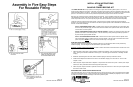
INSTALLATION INSTRUCTIONS
FOR
24H46343 POWER BEYOND KIT
The POWER BEYOND KIT is only required if connecting to an open center tractor hydraulic system. The use of a
power beyond kit allows the connection of the Bush Hog optional control valve to the tractor hydraulics without using the
remote controlled outlets on the tractor. It’s purpose is to protect the normal return port of the Bush Hog valve from back
pressure. Connection to the tractor remove provides this protection through the tractor remote control valve.
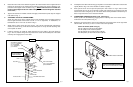
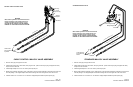
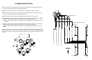
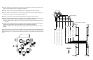
Bush Hog now provides two styles of Walvoil optional control valves: one for standard mounts and one for cable control.
The illustrations show both valves and the hose routing for both. The fittings required to connect the hoses to both
valves are provided in the kit. The power beyond plug for each valve is included in the valve kit ordered separately.
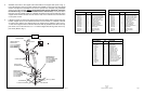
Three lines must be connected to the tractor system. Each line serves a specific purpose and proper plumbing is
essential. The proper location for the connections to the tractor hydraulic system must be obtained from the tractor man-
ufacturer or local tractor dealership.
LINE A - PRESSURIZED SUPPLY LINE — Supplies oil from the pump to the pressure port of the control valve.
This line is the pressurized supply line to the valve when the handle on the optional control valve is activated to
move the boom or bucket cylinder.
LINE B - PRESSURIZED RETURN LINE TO TRACTOR SYSTEM — Returns oil to the tractor system when the
optional control valve is in the neutral position. This line will feel any back pressure generated by operation of
any other tractor system hydraulic function.
LINE C - NON PRESSURIZED RETURN LINE — Returns oil to the tractor system when the optional control
valve is activated to extend or retract the boom or bucket cylinders. This line must be connected to the tractor
system to provide a DIRECT
return of the oil to the tractor sump or oil supply tank.
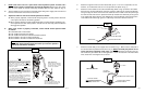
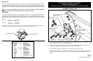
HOSE AND COUPLER ASSEMBLY
The three hydraulic hoses are supplied with reusable couplings for one end while the other end has permanently
installed couplings. The hose length must be determined for your tractor model.
BE SURE
TO MAKE HOSES LONG ENOUGH to attach to tractor when loader is disconnected from tractor and is on its
leg stands.
1. Attach permanent coupler ends of hose to fittings, installed in the pressure, sump and power beyond ports of the
valve. The long hose should be attached to the sump port. See back page for instructions on installing reusable
coupling.
2. Determine required length of each hose, attach reusable couplings to hoses per instructions shown.
3. Install the three adaptors furnished into the hoses on the reusable coupling end. Place the 3/4” JIC end of the
adaptor to hose.
4. Attach two quick coupler female ends to adaptors on the pressure hose and the sump hose. Install a quick coupler
male end, to return pressurized return inlet hose (power beyond hose).
5. Attach two quick coupler male ends to pressure hose and sump hose from tractor. Attach one quick coupler female
end to tractor return outlet.
DISCONNECTING LOADER VALVE FROM TRACTOR
The pressurized supply line, A, and the pressurized return line (power beyond port) must be connected when the loader
valve is removed from the tractor. Insure female and male quick couplers are installed per paragraph 4 above. Failure
to make this connection will result in damage to the tractor hydraulic system.