


15
Initial Setup & Assembly
A
E
C
G
D
B
H
F
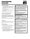
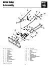
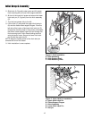
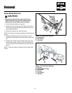
Figure 13. Blade Control Arm Installation
A. Control Arm Support Bracket
B. Flange Nut
C. Bolt
D. Eyebolt
E. Upper Control Arm
F. Lower Control Arm
G. Nut
H. Bolt
E
C
A
D
B
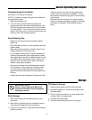
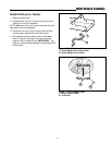
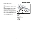
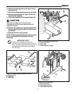
Figure 14. Lower Control Arm Installation
A. Bolt
B. Adjustment Arm
C. Lower Control Arm
D. Ball Joints
E. Hair pins
A
B
C
D
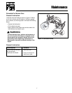
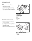
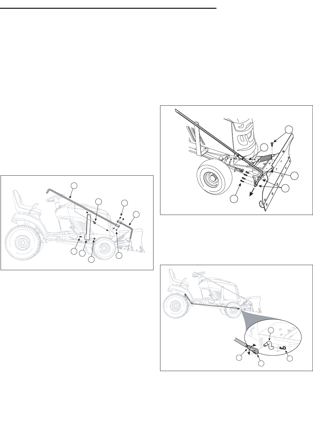
Figure 15. Lower Control Arm Installation
A. Ball Joint
B. Hair pin
C. Bell Crank
D. Ball Joint Lock Nut
Attaching Snow Blade Contort Arm to
Tractor
1. On right side of tractor, install the control arm support
bracket (A, Figure 13) using the flange nut (B) and
bolt (C) to the tractor frame.
2. Install the eyebolt (D) through the hole at the top of
the lift arm support bracket, with the eyebolt to the
outside.
3. Attach the lower portion of the control arm (F) to the
upper control arm using the lock nuts (G) and bolts (H).
4. Install the lock bolt (A, Figure 14)) through the upper
snow blade adjustment arm (B), securing the adjust-
ment arm to the snow blade frame.
5. Slide the control arm through the two adjustment arm
ball joints (D). Secure the control arm with the four (4)
hair pins (E).
6. Lower the blade to the ground and adjust the skid
shoes.
Travel Height Adjustment
1. Fully raise the snow blade off the ground. If the
transport height is not correct, lower the snow blade
to the ground and remove the lift arm (A, Figure 15)
from the bell crank (C).
2. Loosen the lift arm ball joint lock nut (D) and rotate
the ball joint (A) either right or left to adjust the prop-
er lift height.
3. Reinstall and secure the lift arm and test adjustment.
Repeat as needed.