


7
Briggs & Stratton Power Products Home Generator
Installation Manual
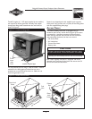
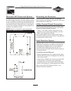
To Remove an Access Door:
1. Insert key into lock of access door you wish to
remove and turn one quarter turn clockwise.
NOTE: The key is retained in the lock when the locks are
open.
2. Grasp door’s lift handle and pull door upwards until
security pins are free of lower base.
3. With the security pins free, pull the lift handle outward
(away) from the unit while pulling the door down and
out of the upper door channel.The door will come
free of the generator enclosure.
The Battery door does not have a lock and the Air Intake
door does not have a lock or lift handle.The Air Intake
door is opened by lifting on the louvers instead of a lift
handle. However, you must remove the door lock screws,
found directly above the center of the doors.
To Install an Access Door:
1. Support door by grasping lift handle or louver. Guide
top of door into generator enclosure.
2. Lift door up into its upper channel until security pins
clear sill of enclosure.
3. Push lower half of door into door recess until it is
flush with sides.
4. Seat door by pushing it down until rubber coated
security pins engage and door rests on mounting sill.
5. If installing a lockable door, turn key one quarter turn
counterclockwise. Remove key.
6. If installing air intake or battery door, replace the door
lock screw.
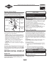
Check to ensure that all the rubber and foam vibration
dampers remain in place.This will minimize vibration noise.
THE GASEOUS FUEL
SYSTEM
TO THE INSTALLER: Consult with the Home
Standby Generator owner(s) and convey any technical
considerations that might affect their installation plans
before applying these general guidelines.
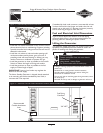
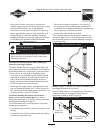
The following general rules apply to gaseous fuel system
piping:
• The piping should be of a material that conforms to
federal and local codes, rigidly mounted and protected
against vibration.
• Piping should be protected from physical damage where
it passes through flower beds, shrub beds, and other
cultivated areas where damage could occur.
• Install the flexible, gaseous hose (supplied) between the
Home Standby Generator Fuel Inlet port and rigid piping
to prevent thermal expansion or contraction from
causing excessive stress on the piping material.
NOTE: Where local conditions include earthquake,
tornado, unstable ground, or flood hazards, special
consideration shall be given to increase strength and
flexibility of piping supports and connections.
The information provided below is to assist
gaseous fuel system technicians in planning
installations. In no way should this information
be interpreted to conflict with applicable fuel gas
codes. Consult with your local fuel supplier or
Fire Marshall if questions or problems arise.
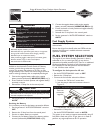
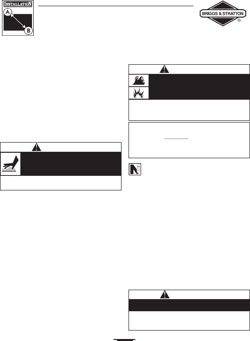
• DO NOT touch hot surfaces.
• Allow equipment to cool before touching.
Running engines produce heat.Temperature of
exhaust port and nearby areas can reach or
exceed 600°F (316°C).
Severe burns can occur on contact.
WARNING
• The entire flexible gaseous pipe must be visible for periodic
inspection and must not be concealed within, contact, or run
through any wall, floor,or partition.
The supplied flexible gaseous pipe is not to be installed
underground or in contact with the ground.
CAUTION
• LP gas is heavier than air and will settle in low areas.
• Natural gas is lighter than air and will collect in high areas.
• The slightest spark can ignite these fuels and cause an explosion.
Propane and Natural Gas is extremely
flammable and explosive.
Fire or explosion can cause severe burns or
death.
WARNING