


14
Briggs & Stratton Power Products Home Generator
Installation Manual
INITIAL START-UP (NO LOAD)
Begin testing the system without any electrical loads
connected, as follows:
1. Set the AUTO/OFF/MANUAL switch to OFF.
2. Set the generator’s main circuit breaker to its OFF
(open) position.
3. Install the 15 Amp fuse in the control panel.
4. Set the AUTO/OFF/MANUAL switch to MANUAL.
NOTE: When the Home Standby Generator is started for
the very first time, it will require that air in the gaseous fuel
lines be purged.This may take a few minutes.
5. DO NOT crank engine for more than 15 seconds, then
pause for 15 seconds to reduce heat in the starter.
6. Repeat process until engine starts.
7. Listen for unusual noises, vibration or other indications
of abnormal operation. Check for oil leaks while the
engine runs.
8. Let the engine warm up for about five minutes to allow
internal temperatures to stabilize.Then, set the
generators main circuit breaker to its ON (or closed)
position.
9. Connect an accurate AC voltmeter and a frequency
meter to check generator output at the load side of
the circuit breaker.Voltage should be 239-262Volts,
frequency should be 62.0 - 62.5 Hz.
NOTE: If either parameter is outside these ranges,
perform the Engine Adjustments described on page 14.
10. Check generator output between one of the generator
connection lugs and the neutral lug, then between the
other generator connection lug and the neutral lug. In
both cases, voltage reading should be between
121-131Volts.
11. Set the AUTO/OFF/MANUAL switch to OFF. Engine
should stop.
IMPORTANT: DO NOT proceed until you are certain
that generator AC voltage and frequency are correct and
within the stated limits.To obtain the proper generator
frequency, see Engine Adjustments on page 14.
Engine Adjustment
There are regional variances in the composition of natural
gas. Each HSG unit is adjusted at the factory for NG
operation. If the generator output voltage or frequency
measured during Initial Start-Up (paragraph #9) is outside
the listed ranges, the combustibility of the gas supplied at
the installation site may be substantially different.
To adjust the engine for this difference, proceed as follows.
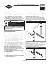
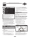
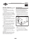
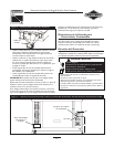
1. Remove the Air Intake and Control Panel access doors.
2. Remove the three M5 sheet metal screws that hold
the control panel wiring cover to the air intake guard
(Figure 13).
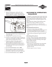
3. Connect an accurate frequency meter to the load side
of the main circuit breaker (on the back of the control
panel).
4. Ensure that the 15 Amp fuse is installed.
5. Set the generator’s main circuit breaker ON.
6. Set the AUTO/OFF/MANUAL switch to MANUAL.
When the engine starts, allow it to warm up for two
minutes.
Figure 13 — Accessing Back of Control Panel