


13
Briggs & Stratton Power Products Home Generator
Installation Manual
NOTE: With the battery installed and utility power
available to the Automatic Transfer Switch, the battery
receives a trickle charge whenever the engine is not
running.This process may take up to 72 hours to fully
charge a battery from 5 Volts.The trickle charge cannot be
used to recharge a battery that is completely discharged.
5. Connect the negative battery cable to the negative
battery terminal (indicated by NEGATIVE, NEG, or (-).
6. Ensure hardware on both positive and negative battery
terminals is secure.
7. Reinstall the 15 Amp fuse in the control panel.
8. Set the generator's “AUTO/OFF/MANUAL” switch to
AUTO.
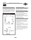
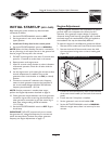
Servicing the Battery
If it is necessary to service the battery, proceed as follows:
1. Set the generator's “AUTO/OFF/MANUAL” switch to
OFF.
2. Remove the 15 Amp fuse from the control panel.
3. Service or replace battery as required.
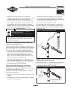
4. Connect the red battery cable to the battery positive
terminal (indicated by POSITIVE, POS, or (+).
5. Connect the negative battery cable to the negative
battery terminal (indicated by NEGATIVE, NEG, or (-).
6. Ensure hardware on both positive and negative battery
terminals is secure.
7. Reinstall the 15 Amp fuse in the control panel.
8. Set the generator's “AUTO/OFF/MANUAL” switch to
AUTO.
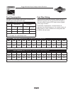
Fuel Supply System
Ensure that all fuel pipe connections are tight, secure and
without leaks.
Ensure that all gas line shutoff valves are OPEN and that
adequate fuel pressure is available whenever automatic
operation is desired.
FUEL SYSTEM SELECTION
The engine of your Home Standby Generator is factory
calibrated to run on natural gas (NG). It may also be
operated on liquefied petroleum (LP).There is no additional
hardware/equipment required to switch between either
fuel. However, LP fuel inlet pressure must be between
11 and 14 inches water column.
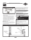
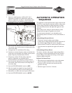
To configure the fuel system for LP use:
• Set the AUTO/OFF/MANUAL switch to OFF.
• Remove the 15 Amp fuse.
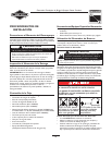
• Connect the fuel transfer solenoid as follows:
1. Remove the “Oil Service” access door.
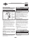
2. Join the two-pin electrical connector shown in
Figure 12.
3. Reinstall the “Oil Service” access door.
• Reinstall the 15 Amp fuse.
• Set the AUTO/OFF/MANUAL switch to AUTO.
The system is now ready to operate automatically using LP
fuel.With a fixed main jet for LP gas, there is no need to
perform any engine adjustments for LP operation.
• DO NOT install the 15 Amp fuse until all plumbing and wiring
has been completed and inspected.
Installing the 15A fuse could cause the engine to start.
CAUTION
• DO NOT dispose of battery in a fire.
• DO NOT allow any open flame, spark, heat, or lit cigarette
during and for several minutes after charging a battery.
• DO NOT open or mutilate the battery.
• Wear protective goggles, rubber apron, and rubber gloves.
• Remove watches, rings, or other metal objects.
• Use tools with insulated handles.
Storage batteries give off explosive hydrogen gas
during recharging.
Slightest spark will ignite hydrogen and cause
explosion.
Battery electrolyte fluid contains acid and is
extremely caustic.
Contact with battery contents will cause severe
chemical burns.
A battery presents a risk of electrical shock and
high short circuit current.
DANGER
Figure 12 — Fuel Transfer Solenoid Connection
Push two
connectors
together