


6
Briggs & Stratton Power Products Home Generator
Installation Manual
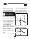
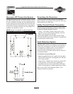
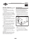
Two 48” lengths of 1” O.D. pipe (supplied by the installer)
are required to lift the generator manually. Insert pipes
through the lifting holes located near the unit’s base, as
shown in Figure 3.
You may also lift the unit using a “hook and hoist” method
attached to the lifting pipes, provided that you use a
spreader bar to ensure that the chains or cables do not
touch the generator’s roof.
Retouch any chipped paint with supplied touch-up paint.
After paint is dry, and the unit is in place, fill the lifting holes
with the supplied lifting hole plugs.
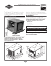
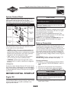
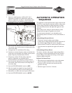
Access Doors
The Home Standby Generator is equipped with an
enclosure that has four access doors (Figure 4).The doors
are named for a significant component located behind
them. Starting with the side that has the fuel connection
and proceeding clockwise, the doors are named:
• Oil Service door
• Air Intake door
• Control Panel door
• Battery door
Each Home Standby Generator is equipped with three
identical keys.These keys fit the locks that secure the Oil
Service and Control Panel doors.
Fuel
Inlet
Exhaust
Port
Door Lock
Screw
Door
Lock
Screw
Battery Door
Control Panel Door
42”
30”
29”
Figure 4 — Enclosure Access Doors
Air Intake Door
Oil Service Door
To lift:
Insert
pipe
here
Installer-supplied pipe
Figure 3 — Location of Lifting Holes
CAUTION
• Failure to install Oil Service and/or Control Panel doors while
operating the Home Standby Generator will cause overheating.
DO NOT operate the Home Standby Generator unless
the Oil Service and/or Control Panel doors are installed.