4-14 Operation MN2417
Analog Inputs
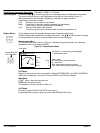
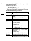
Three analog inputs for resistive sensor 0 to 2400 ohms measuring are available on IL controller.
Use LiteEdit software to modify configuration.
The Analog inputs values assignment (AI1 = Oil press, AI2 = Water temp, AI3 = Fuel level) is fix.
It is possible to configure on each Analog input:
S Reading from IL Analog inputs or from Engine Control Unit via CAN bus (J1939)
S Sensor characteristics − from the list,
S Value dimension (e.g. psi − bars, °F − °C, % − l)
S Number of decimal points (0, 1, 2,
...).
Note: Corresponding Analog input terminal is dead when reading is switched to ECU.
All values from ECU shall show ####, but no alarm is displayed when CAN communication
is interrupted.
Warning and shut−down limits are adjusted in Engine protection group.
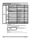
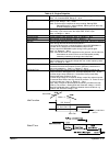
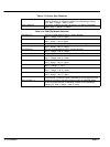
Table 4-8 Analog Inputs
AI1 Oil press Oil pressure analog input. Default VDO sensor in range 0 to 145 psi.
AI2 Water temp
Water temperature analog input. Default VDO sensor in range 32 to 212°F
AI3 Fuel level Fuel level analog input. Default VDO sensor 0−180R = 0−100%.
Set points
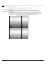
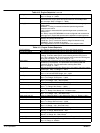
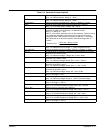
Table 4-9 Basic Setpoints
EnterPassword Password is a four−digit number. Password enables change of relevant
protected set points Use ⇑ or ⇓ keys to set and ENTER key to enter the
password.
ChangePassword Use ⇑ or ⇓ keys to set and ENTER key to change the password.
Gen−set name User defined name, used for InteliLite identification at remote phone or
mobile connection. Gen−set name is max 14 characters long and have to
be entered using LiteEdit software.
Nomin power(3ph) Nominal power of the generator in three phases connection.
Step: 1 kW; Range: 1 − 3000 kW
Nomin power(1ph) Nominal power of the generator in single−phase connection.
Step: 1 kW; Range: 1 − 3000 kW
CT Ratio Gen−set phases current transformers ratio.
Step: 1 A; Range: 1 − 5000 A / 5A
PT ratio Gen−set potential transformers ratio.
Step: 0,1 V / V; Range: 0,1 − 500,0 V / V
Nominal freq Nominal generator frequency (usually 50 or 60 Hz )
Step: 1Hz; Range: 45 − 65 Hz
Gear teeth Number of teeth on the engine gear for the pick−up. Set to zero, if no
pick−up is used. Engine speed is counted from the generator frequency.
Step: 1; Range: 0 − 500
Note: Generator frequency can be used only when generator voltage
(min 5V) is present before reaching of the firing speed
(Starting RPM) after start.
Nominal RPM Nominal engine speed. Step: 1RPM; Range: 100 − 4000 RPM.
FLTRESGOTOMAN DISABLED: Controller stays in AUT mode after Fault reset .
ENABLED: Automatic switch from AUT (or TEST) to MAN mode after
Fault reset to avoid automatic engine start. This function is active for Shut
down protection only.
DispBackLightTO Timeout after which the display backlight is switched off.
Step: 1 min Range: 0 − 60 min
Default value: 0 = the display lights all the time
Mode IL [ OFF, MAN, AUT ]
Equivalent to Controller mode changes by MODE" or MODEA buttons.
Note: Controller Mode change can be separately password protected.
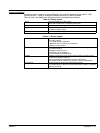
RS232 mode
[Standard/Modbus ]
Communication protocol switch.
Standard: LiteEdit communication protocol. Modbus: Modbus protocol.
Note: For detail description see chapter Modbus protocol.
Num rings AA Number of rings prior to open modem connection. Step: 1; Range: 1 − 30
Note: NumberRings AA change is not activated immediately. It is activated
after controller is switched on or when modem is connected to controller.


