


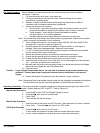
Operation 4-7MN2417
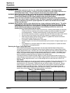
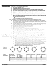
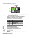
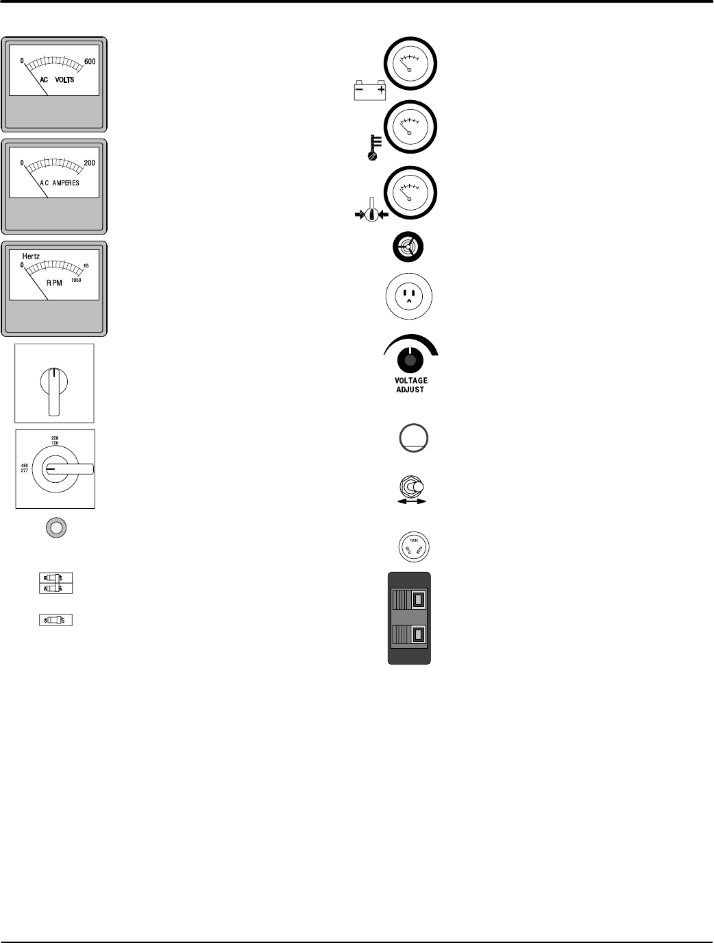
Figure 4-5 Operator Control Panel Components
PANEL LIGHTS
ON OFF
Panel Lights switch (On−Off )
Turns on the panel lights.
FUSE
Fuse Fuses provides protection on some units.
(Do not remove while generator is running).
BREAKER
Breaker Circuit Breakers provides protection on
some units. To reset a breaker, simply press
the center button when tripped or move
handle to Off" then back to On".
Shore Power Inlet Connect an extension cord that
has an appropriate rating from utility power to this
outlet. To power onboard battery charger, block
heater, etc.
Horn A Horn (annunciator or buzzer) sounds an
alarm when operator attention is needed.
Voltage Select Switch switch
Selects 208/120, 240/120 or 480/277VAC.
OFF
1
2
Auto Start Connection for external two wire starting from
transfer switch or other controller. Strip the
insulation from the remote start wires. Simply
press while inserting the wire then release to
secure the connection.
Panel Lights)
Lamps to illuminate the operator panel.
Amps Switch switch (On−Off )
Selects what is displayed on AC
Amperes meter.
Off − No AC Ampere display.
1 − Phase 1 current display.
2 − Phase 2 current display.
3 − Phase 3 current display.
Volts
Analog display of generator output voltage
in RMS volts.
AMPS
Analog display of generator output current
in RMS amps.
HERTZ
Analog display of generator RPM which
relates to the output frequency in Hertz.
Battery
Displays the voltage of the engine starting battery.
Water Temp
Displays the temperature of the engine coolant.
Oil Press
Displays engine oil pressure.
Voltage Adjust
Increase or Decrease the Generator output
voltage.
−+
or
or
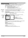
15
1 Pole
2 Pole
Note: Some features are optional and
may not be installed on your system.
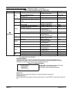
Voltage Reconnect and Adjustment
The digital engine controller runs software called voltage auto−detect. Every time the engine is
started and after the timer in the Engine Params: Stabil Time has elapsed, the nominal voltage
will be detected and locked in. Various set points in the engine controller are then calculated as
a percentage of this nominal voltage. For example: The over−voltage set point is set to 110%.
This means that when the unit is providing 208V, the over−voltage set point will lock in at 229V.
When the unit is operating in 480V the over−voltage set point will lock in at 528V.
Example: To change the voltage from 208V nominal to 240V nominal, the voltage adjustment
must be made before the controller locks in the nominal voltage.
1. Set the Voltage Select Switch to 240/120V position.
2. Start the engine.
3. Immediately adjust the Voltage Adjust for 240VAC nominal before the 20 second timer
expires.
4. The new 240V nominal voltage is now locked in.
This procedure must be performed whenever the nominal voltage is changed.