


4-4 Operation MN2417
Towing Instructions
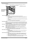
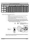
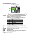
See Figure 4-1 for component identification.
1. Be sure the generator is off.
2. Shut all enclosure doors and latch the locks.
3. Back the tow vehicle to within a few inches of the trailer coupler (Pintle or Ball).
4. Be sure the Coupler Handle is in the “UP” (open) position or the Pintle Hook is Open.
5. Adjust the trailer jack for the height of the hitch on the tow vehicle.
6. Back the tow vehicle so the trailer coupler is directly over the tow vehicle ball hitch or
the Pintle hook.
7. Lower the trailer so the trailer coupler rests securely on the ball hitch of the tow vehicle.
Move the Coupler Handle to the horizontal position and lock it in place to securely hold
the ball hitch of the tow vehicle.
OR
Latch the Pintle and lock the Pintle device securely.
Note: If this is not done properly, the trailer may become unhitched when it is towed.
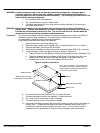
8. Retract the front jack, pull the jack pin and rotate the jack 90 degrees from vertical to
the horizontal position, making sure the self−locking pin reseats and the jack is secured
to the tow bar (stowed position).
9. Connect safety chains, making sure to cross them. If a safety chain is too long, simply
twist it a few turns to shorten the chain before attaching to the tow vehicle.
10. Connect the trailer light connector to the tow vehicle.
11. Test the trailer lights to ensure they are operational.
12. Check tires for proper inflation.
13. Check wheel lug nuts for correct tightness (see Lug Nut Tightness).
Wheel nuts/bolts should be torqued before the first road use and after each wheel
removal. Check and re−torque after the first 50 miles and again at 100 miles.
Check periodically thereafter.
14. Verify that all jacks, pins, cables, and doors are secured and trailer tongue is level.
15. Remove tire chocks (if used). These prevent the trailer from moving when parked.
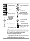
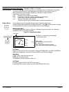
Lug Nut Tightness
Be sure to use only the fasteners matched to the cone angle of your wheel (usually 60 or 90
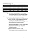
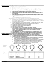
degrees.) The proper procedure for attaching your wheel is as follows, see Figure 4-2:
1. If a wheel is removed and installed, start each nut by hand to prevent cross threading.
2. Tighten lug nuts in the following sequence.
a. Tighten each bolt in the sequence shown in Figure 4-2 and tighten to one half the
torque specified until all lug nuts are tightened to one half the torque.
b. Tighten each bolt in the sequence shown in Figure 4-2 and tighten to three fourths
the torque specified until all lug nuts are tightened to three fourths the torque.
c. Tighten each bolt in the sequence shown in Figure 4-2 and tighten each to the
specified torque until all lug nuts are tightened to the correct torque.
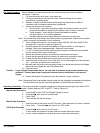
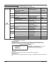
Figure 4-2 Lug Nut Tightening Specifications
Description
1/2” Cone nut
5/8” Cone nut
5/8” Cone nut
3/4” Hex nut
4 Bolt 5 Bolt 6 Bolt 8 Bolt 10 Bolt
Tightening
Sequence
Application
12” − 13” Wheel
14” − 16” Wheel
Flat Disc Wheel
Clamp Ring
Demountable Ring Clamp
Minimum Torque (ft−lbs.)
50
90
175
190
210
Maximum Torque (ft−lbs.)
65
120
225
210
260
Torque
Specification
1
2
34
1
2
34
5
7
68
1
2
34
5
1
63
2
45
1
2
63
8
10
5
7
9
4