


4-6 Operation MN2417
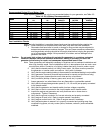
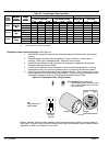
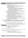
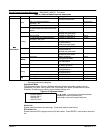
Table 4-2 Three/Single Phase Operation
Alternator
Voltage
Voltage at Terminal Lugs Voltage at Plug Receptacles
Switch
Position
Alternator
Winding
Connection
Voltage
Adjust
Position
Line To Line Voltage Line To Neutral Voltage
120VAC
Receptacles
240VAC Receptacles
(Twist Lock)
Position
C
onnec
ti
on
P
os
iti
on
L1−L2 L2−L3 L1−L3 L1−N L2−N L3−N L−N L−L L−N
Series High
Minimum 416 416 416 240 240 240 120 208 120
480/277
Series High
Wye
Middle 460 460 460 266 266 266 133 230 133
480/277
W
ye
Maximum 480 480 480 277 277 277 139 240 139
Parallel Low
Minimum 208 208 208 120 120 120 120 208 120
208/120
Parallel Low
Wye
Middle 230 230 230 133 133 133 133 230 133
208/120
W
ye
Maximum 240 240 240 139 139 139 139 240 139
Parallel Low
Minimum
200 100
100 100 200 100
240/120
Parallel Low
ZigZag
Middle
220 110
110 110 220 110
240/120
Zi
g
Z
ag
Maximum
240 120
120 120 240 120
No connection at Terminal Lug #2.
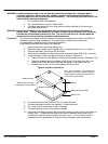
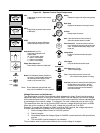
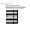
Receptacle Panel Load Connections, see Figure 4-4.
1. 240/120VAC voltage is present at the receptacle panel at all times when generator is
running.
2. Carefully inspect all Individual load cables for broken insulation or other signs of
damage. Never use a damaged cable. Replace it before usage.
3. Individual load cables may be routed into the receptacle compartment through the
Enclosure Electrical Access Panel.
4. Individual load cables may be connected or disconnected while generator is running.
Use extreme care not to touch any electrical wire or terminal to avoid shock hazard.
5. Keep Enclosure Electrical Access Panel closed at all times. This prevents rain or other
harmful elements from entering the compartment. Output metering and gauges can be
observed through the window in the Enclosure Electrical Access Panel.
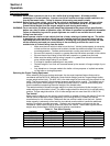
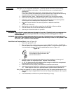
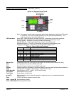
Figure 4-4 Receptacle Panel (Single Phase)
Note:
Single phase power is
always available.
(GOLD)
X
(GOLD)
Y
G
W
(SILVER)
CS6369
125/250V
50A
X
Y
W
Test
Reset
CS6365N
GFI Outlet
120V, 20A
240V, 50A
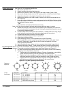
Circuit Breakers (Single or Double pole)
Circuit Breakers provides protection on some
units. To reset a breaker, place it in the OFF
then the ON position.
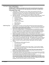
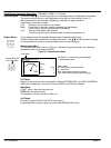
Meters, switches, lights and other operator control components are located in various places on
each panel. Figure 4-5 can be used to identify the function and features of each operator control
regardless of where it is located on your panel.