


3-4 Receiving & Installation MN2417
Electrical Connections Class 1 wiring methods must be used for field wiring connections to terminals of a class 2
circuit. It is the responsibility of the owner/operator to arrange for these procedures to be
performed by a licensed electrical contractor and ensure conformance to all applicable codes
including local codes peculiar to your municipality/city/county and state. Wire size and insulation
type should be as required by NEC (National Electrical Code) and local codes.
Warning: Never connect this generator to the electrical system of any building unless a licensed
electrician has installed an approved transfer switch. The national electrical code (NEC)
requires that connection of a generator to any electrical circuit normally powered by means of
an electric utility must be connected by means of approved transfer switch equipment to
isolate the electrical circuit from the utility distribution system when the generator is
operating. Failure to isolate the electrical circuits by such means may result in injury or death
to utility power workers due to backfeed of electrical energy onto the utility lines.
Warning: Incorrect installation of this generator set could result in property damage, injury or death.
Connection of the generator to its fuel source must be done by a qualified professional
technician or contractor.
WARNING: Be sure the system is properly grounded before applying power. Do not apply AC power before
you ensure that grounds are connected. Electrical shock can cause serious or fatal injury. NEC
requires that the frame and exposed conductive surfaces (metal parts) be connected to an
approved earth ground. Local codes may also require proper grounding of generator systems.
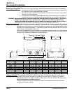
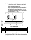
Intended Use The intended purpose of this generator set is to provide electrical power when the main utility power
supply is interrupted. Therefore, it is important that all the wiring that connects the generator set with
your house, transfer switch, distribution box, battery charger, etc. be properly installed.
Protection Single Phase circuit protection is provided within the generator. The power output connections
are rated and sized according to the KW of the generator. Proper lead wire from these points to
the automatic transfer switch (or load switching device) is mandatory. See transfer switch
information for corresponding generator input terminals.
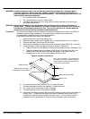
Three phase circuit protection is provided by the generator. When connecting the generator
output to an electrical load, a UL listed circuit breaker with the appropriate ratings shall be
provided within 25 feet of the Genset. Use only copper wires.
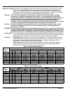
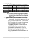
Table 3-3 Standby Power Ratings
Generator
Electrical Load Capacity Standby Power Ratings
Generator
Catalog
1 Phase 3 Phase
Catalog
No.
kVA kW Volts Amps * kVA kW Volts Amps
TS25 18 18 240/120 75/2x75 25/25/25 20/20/20 208/240/480 69/60/30
TS35 25 25 240/120 104/2x104 37/37/37 30/30/30 208/240/480 104/90/45
TS45 27 27 240/120 112/x2112 46/46/48 37/37/38 208/240/480 128/111/57
TS60 43 43 240/120 179/2x179 60/60/61 48/48/49 208/240/480 166/144/73
TS80 45 45 240/120 187/2x187 72/72/81 58/58/65 208/240/480 201/174/97
TS130 70 70 240/120 291/2x291 131/131/134 105/105/107 208/240/480 364/315/160
TS175 100 100 240/120 416/2x416 169/169/175 135/135/140 208/240/480 468/405/210
TS250 175 175 240/120 729/2x729 250/250/250 200/200/200 208/240/480 693/601/300
TS400 250 250 240/120 1041/2x1041 400/400/400 320/320/320 208/240/480 1110/962/481
* Example 2x75 means 2 lines (Line to Neutral) of 120V @ 75 amps each.
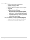
Table 3-4 Prime Power Ratings
Generator
Electrical Load Capacity Prime Power Ratings
Generator
Catalog
1 Phase 3 Phase
Catalog
No.
kVA kW Volts Amps * kVA kW Volts Amps
TS25 18 18 240/120 75/2x75 23/23/23 18/18/18 208/240/480 62/54/27
TS35 22 22 240/120 91/2x91 33/33/33 27/27/27 208/240/480 93/81/40
TS45 25 25 240/120 104/2x104 44/44/44 35/35/35 208/240/480 121/105/52
TS60 40 40 240/120 166/2x166 56/56/56 45/45/45 208/240/480 156/135/67
TS80 43 43 240/120 179/2x179 69/69/75 55/55/60 208/240/480 190/165/90
TS130 66 66 240/120 275/2x275 119/119/121 95/95/97 208/240/480 329/285/145
TS175 95 95 240/120 395/2x395 156/156/159 125/125/127 208/240/480 433/375/190
TS250 160 160 240/120 666/2x666 227/227/227 180/180/180 208/240/480 624/541/270
TS400 240 240 240/120 1000/2x1000 365/365/365 292/292/292 208/240/480 1013/878/439
* Example 2x75 means 2 lines (Line to Neutral) of 75 amps each.