slightly to accomplish this; however, do not exceed
–-20 dBm output power.
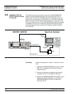
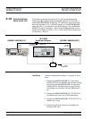
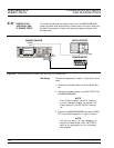
4. Remove Connection A and connect the 682XXB/
683XXB RF OUTPUT to the waveguide mixer in
-
put of the Spectrum Analyzer as shown in Con
-
nection B.
5. On the 682XXB/683XXB, remove 30 dB of at
-
tenuation from the RF output. Do this by either
increasing the output power level by 30 dB or by
removing the 30 dB attenuator installed in step
1.e.
6. Change the Spectrum Analyzer CF to the har
-
monic frequency listed on the Test Record. Verify
that the signal displayed on the Spectrum
Analyzer is ³30 dB below the top of the screen
graticule.
NOTE
The <–30 dB signal level plus the 30 dB at-
tenuation provided by the waveguide
mixer equals a harmonic frequency signal
level of <–60 dBc (specification).
7. Record the harmonic signal level on the Test Re-
cord.
8. Repeat steps 1 through 7 for each of the 682XXB/
683XXB CW carrier and harmonic frequencies
listed on the Test Record. Record the harmonic
signal levels on the Test Record.
682XXB/683XXB MM 3-21
PERFORMANCE HARMONIC TEST: RF OUTPUT
VERIFICATION SIGNALS FROM 2 TO 20 GHz


