


MAINTENANCE
VERSA 03/09 Maintenance Section 4-9
© 2009 Alamo Group Inc.
MAINTENANCE
CLEANING
1. Clean housing and all related parts thoroughly and dry.
2. Protect parts from contamination.
INSPECTION
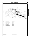
Bearings and cups: Inspect rollers, races, and cages for nicks, pitting, discoloration, and signs of excessive
or unusual wear. Replace any worn or damaged parts.
Spindle shafts: Inspect the threads, internal splines, and bearing journals for damage or wear. Replace if
damaged or worn.
Bearing ring: Inspect the ring for wear in the area of seal contact. Replace if a wear groove exists.
Housing: Inspect the bearing cup bores, ring grooves, etc. for wear or damage. Repair or replace if any
damage is found.
Tools needed:
Hand tools Hydraulic press
Inch pound torque wrench Seal Installers
Bearing drivers (do not use punches Adjusting nut socket
to install bearings) 2-3/4" ID x 8" long, 16 Ga. tubing
Note: This procedure should not be attempted in the field due to the need for tools normally only found
in the shop.
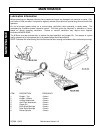
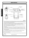
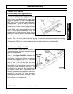
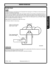
1. Place upper bearing cones in bearing oven.
2. Seat bearing cups (outer races) in housing using a press and proper installation tools in good condition.
CUPS MUST BE FULLY SEATED. If bearing cup cocks in bore and seizes, do not continue to assemble
spindle.
3. Lubricate lower bearing cone with LPS.
4. Coat the outside of the seal with silicone and install the lower bearing, seal, and retaining ring into the
housing, using the correct seal installer.
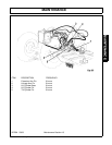
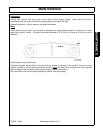
5. Place a light film of silicon or permatex on the inside diameter of the bearing ring and seat the ring on the
spindle shaft, using the proper tool and press.
6. Lightly lubricate the lip of the seal.
7. Using the 2-3/4" tubing to prevent the cup and cone from contacting each other, press the spindle shaft
through the lower bearing and seal. Make sure the bearing is seated against the bearing ring.
8. Place Locktite on threads of the bearing adjusting nut (flange nut).
9. Using gloves, install the heated upper bearing cone on the shaft immediately and push it all the way
against the cup. Lubricate the bearing with LPS.
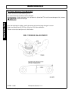
10. Install the bearing adjusting nut. Tighten the nut until the spindle shaft can not be turned. Loosen the nut
1/4 turn. Place a soft, clean cloth over the top of the spindle assembly. Place an aluminum block over the
end of the spindle shaft and strike the block with a hammer to loosen the bearing.
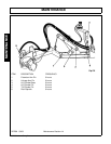
11. Remove the cloth, being careful not to allow any contamination into the spindle. Tighten the nut until a
rolling torque of 16-21 inch-pounds is reached. (If the seal was not lubricated, add 10 inch-pounds).
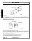
12. Stake the nut with a blunt, round nosed punch. Do not tear the nut.
13. Install the grease fitting into the hole in the center of the housing (between the bearings) and fill the
housing with EP#2 grease (P/N 00900000), stopping when the lubricant covers the upper bearing
(approximately 11 oz.).
14. Install the breather plug in the top hole.
15. Install spindle in mower deck and assemble in reverse order. Torque the blade bar or pan bolts to 400 ft-
lbs. Torque motor to spindle bolts to 85 ft-lbs. Torque spindle to deck bolts at 175 ft-lbs.