


ASSEMBLY
VERSA 03/09 Assembly Section 3-7
© 2009 Alamo Group Inc.
ASSEMBLY
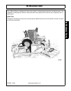
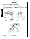
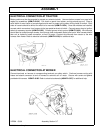
ELECTRICAL CONNECTION AT TRACTOR
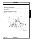
Battery cable must be disconnected to prevent any electrical shock. Unscrew bottom screws from panel with
regular tip screwdriver (ASM-FL-0104). Pull down on panel from bottom, and top should pop out. Place a
small block of wood inside of console against side wall to protect wiring when drilling holes for switch. Both
sides of console should be drilled for switch to be mounted (ASM-FL-0104). Once the switches are installed,
connect switch connectors from harness to the top spade terminals of switch. Connect power wires to ignition
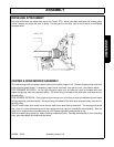
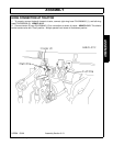
switch at accessory terminal (ASM-FL-0105). Connect ground wire to ground (ASM-FL-0105). Wire harness
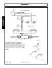
should then be routed through console, then through hole underneath seat at pivot point. Wire harness should
then exit at hydraulic hoses connection, at front of tractor. Connect wire harness from tractor to the wire
harness from mower. Refer to electrical schematic (ASM-FL-0106) for additional help.
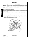
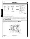
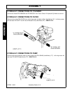
ELECTRICAL CONNECTION AT MOWER
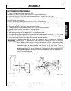
Connect terminals on harness to corresponding terminals on safety switch. Continue harness routing with
hoses and attach connector at end of harness to solenoid coil on motor. Secure with screw and gasket
provided with harness. ASM-FL-0106. Refer to electrical schematic (ASM-FL-0107) for additional help.