


© 2005 Alamo Group Inc.
Section 7 - 12
Switch Blade (JD-5105-5205-5225-5325-5425-5525, Asy. Man) 05/05
KNIFE DRIVE REPAIR / REPLACEMENT
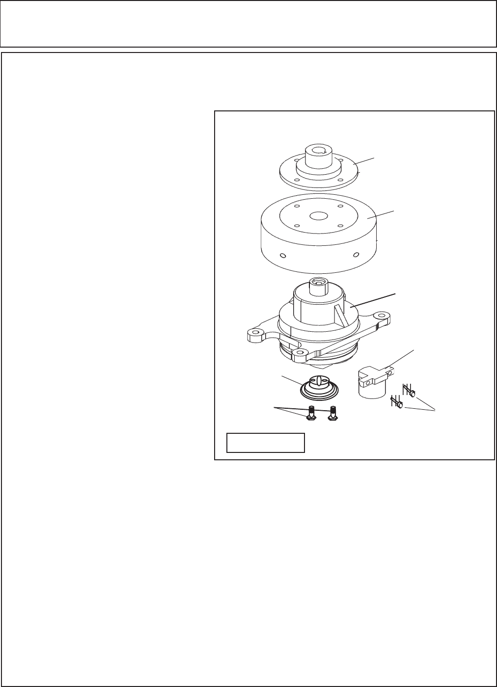
Knife Drive Assembly Repair / Replacement:
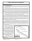
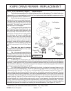
1. The knife drive assembly will be limited to the parts that can be replaced. The Actual knife drive
subassembly is not a repairable part and will not have replacement parts available, components on the
knife drive assembly can be replaced only.
Hub Adapter
Flywheel
Knife Drive
Sub-Asy
Knife Drive
Stud Bearing
Knife Drive
Stud Brg Mnt
Bolts
Support
Support Mnt
Bolts
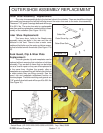
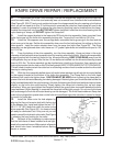
2. It will not be require to remove any of
the hydraulic hoses or even take them loose.
The Motor can be unbolted from the drive
assembly and laid aside with the hoses still
connected. The motor has a splined shaft
that mates to the hub adapter.
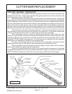
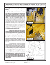
3. Looking down at the planetary drive
(and Hydraulic Motor Assembly) there are
four nuts in the plate that is attached to the
drive assembly. Remove these four nuts, if
you want to remove the four carriage bolts
the skid shoe will have to unbolted and
removed. When lifting the drive assembly
up and away from the cutter bar take notice
of the four tube spacers under the drive
assembly, there are two different length of
the spacers. The short ones go to the rear
and the long ones go to the front (See Figure
22)
4. There are two ways to remove
the knife drive assembly from the cutter
bar knife head weldment.
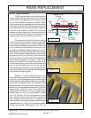
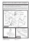
5. 1 st. is to remove the two knife drive
bolt that retain the knife drive stud to the drive
assembly support bracket, this allows the
drive stud bearing assembly to stay with the
cutterbar (See Figure 27) .
Figure 27
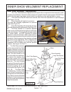
6. Or 2 nd. there is a clamp bolt on the Knife Head Weldment, loosen the clamp bolt, this will allow
the Knife drive stud bearing to pull out of the knife head weldment clamp or off the knife drive stud bearing
assembly. (See Figure 23 & 24) Once the drive assembly has been lifted off you will see a nylon bearing
in the knife bar head clamp, it should have stayed in the clamp or it could have stayed on the knife drive
stud bearing assembly (See Figure 23 & 27)
7. The Hub Adapter is bolted to the Flywheel with four bolts, the flywheel is pressed down over the
top shaft of the drive subassembly. The Knife stud bearing support bolts to the bottom of the drive
subassembly with two bolts. The Knife drive stud bearing bolts to the support bracket (See Figure 27).
If you unbolted the stud drive and left it in the cutter bar it should be removed and inspected. This stud
drive is a sealed bearing drive assembly, there are no replaceable parts in it so it can only be replace as
an assembly. To check the stud drive bearing assembly hold the top where the two bolts mount it to the
support bracket. Grab the OD of the stud drive and the outer cover should spin freely while the top for
the two bolts will not, it should not be rough or out of round. To work properly it must be free and smooth
turning. Check the nylon bearing in the knife head weldment, it has to be in good condition also. This nylon
bearing does not turn when installed, it acts solely as a bushing between the clamp and stud drive bearing
assembly and prevent the clamp from crushing the drive stud bearing. (See Figure 22, 23 & 27)