


© 2005 Alamo Group Inc.
Section 4 - 4
Switch Blade (JD-5105-5205-5225-5325-5425-5525, Asy. Man) 05/05
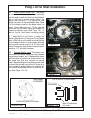
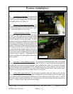
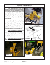
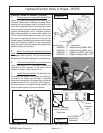
7. Cutter Head Assembly. The Cutter head
Assembly is shipped completely assembled with
the Skid Shoe, Actuator Pre-Assembly, Carriage
Arm, Hydraulic Cylinders, Hydraulic Motor, Drive
Assembly, Motor Cover and Cutter Bar Assem-
bly attached (See Figure 4). To mount this the
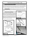
carriage Arm (See Figure 5) which has the Car-
riage Arm Mounting pin installed in it when shipped
will have to have the pin removed (See Figure 4
pin is removed).
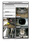
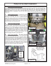
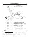
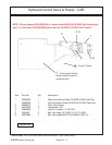
8. Install Cutter Bar Head Assembly Using
an over head hoist lift and slide the cutter bar
assembly into place until the carriage arm is in
alignment with the sub-frame (See Figure 1 )
mounting holes. Insert the carriage arm mount-
ing pin (See Figure 5, 6 & 7) and the two retain-
ing bolts and nuts that were in the retaining pin
when it was removed from the carriage arm.
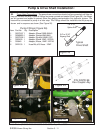
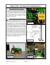
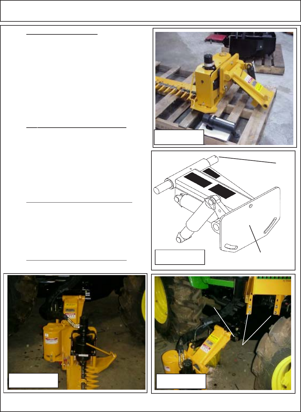
9. Install The Hydraulic Tank Assembly. The
hydraulic tank is shipped as an assembly with
the filter and directional solenoid valve attached
to it. The Hydraulic tank will bolt to the frame (See
Item 4 Figure 1) with 4 bolts, lockwashers and
Nuts (See Figure 1 & 7)
10. Make Certain Bolts are Tightened. Make
certain that the mounting bolts so far are tight.
Figure 4
Carriage Arm Asy
Carriage Arm Pin
Figure 5
Figure 6
Figure 7
Tank
Mounting
Bolts
Carriage
Arm Pivot
Pin
Frame Installation