


© 2005 Alamo Group Inc.
Section 4 - 5
Switch Blade (JD-5105-5205-5225-5325-5425-5525, Asy. Man) 05/05
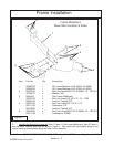
Mount Kit Component Identification
Figure 8
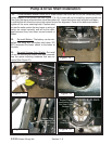
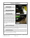
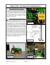
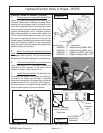
11. Install Operators Manual Cannister. The
operator manual cannister bolts to the hydraulic tank
on the side toward operator, this cannister should
have the operators manual inside of it when shipped
from the factory (See Figure 8). Note: The hydrau-
lic tank has the return filter and directional control
valve (Solenoid) already connected to it when
shipped from the factory.
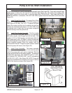
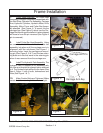
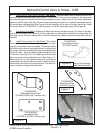
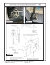
12. Install Valve Control Handle Mounting Brack-
ets. The valve control stand weldment (P/N 107352)
will bolt to the flat operators platform on the RH side.
Install the mount stand where it will be convenient
for the operator to use. The control stand weldment
is adjustable for height, this is done by selecting
the mounting hole you want to use. The stand can
be cut for height adjustment if wanted. The valve
control bracket (P/N 02977335) bolts the stand
weldment using the holes that best fir the opera-
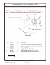
tors needs (See Figure 9 & 10). Once the right dis-
tance is decided to fit operator the valve control
mount will bolt to the floor of the operators plat form
with 4 bolts. The holes will need to drilled through
the floor, check the under side of the floor before
drilling any holes to make certain drill bit will not hit
and damage anything (See Figure 11).
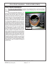
Operators Manual
Cannister
Motor Directional
Control Valve
Return Filter
Assembly
Hydraulic Tank
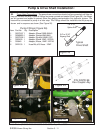
P/N 02977335
Valve Mount Brkt
Weldment
P/N 107352
Control Stand
Weldment
Figure 9
Figure 10
Figure 11