


© 2005 Alamo Group Inc.
Section 3 - 8
Switch Blade (JD-5105-5205-5225-5325- 5425-5525, Asy. Man) 05/05
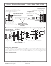
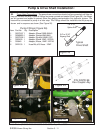
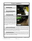
Figure 13
Spline Hub
P/N 02702900
Hub Mountiing Bolts
and Washers (4 ea)
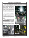
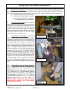
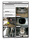
11. Modify Tractor Bolster Front. The bolster
of the tractor will need a hole cut into it that aligns
with the engine crank shaft, this hole should be cut
with a hole saw to prevent jagged edges. The
bolster has a DIMPLE in it in the front to show
where the center of the crankshaft is (See Figure
14), this dimple is cast into the bolster when it is
made. Using a Minimum of a 1-1/2" dia. hole saw
cut a hole into the bolster using this dimple as a
centering reference point (See Figure 15). It is
best to cut this hole before reinstalling bolster
cover, but if you have already reinstalled it us a 2"
X 4" wood block to hold cover up away from
bolster (See Figure 15) noting cover is not bolted
down. After hole is cut in bolster note that the hole
is not closed at the top, the amount open at the top
will vary with the size hole cut. A 7/8" drive shaft
will go through this hole, Alamo Industrial recom-
mends a 1-1/2" dia hole minimum.
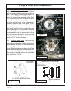
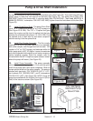
12. Reinstall Bolster Cover. The bolster cover
will install in the same manner as it was removed
see previous steps 4 and 5. Make certain that no
electrical wires are where the should not be. Use
the same bolts that were removed to reinstall
cover. Before bolting the cover down you will need
to check the fit where you cut the half circle out to
clear crankshaft pulley adapter and splined hub,
this should be checked from the top and the bot-
tom (See Figure 17 & 18).
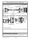
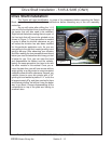
JD-5425 & JD-5525
Shown
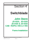
Figure 12
Crankshaft
Pulley
Pulley
Adapter P/N
02973992
Existing 4
Bolts &
Washers
JD-5425 & JD-5525
Shown
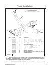
Pump & Drive Shaft Installation:
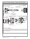
Figure 13A
Pulley Adapter
P/N 02982837
Tractor Engine Pulley
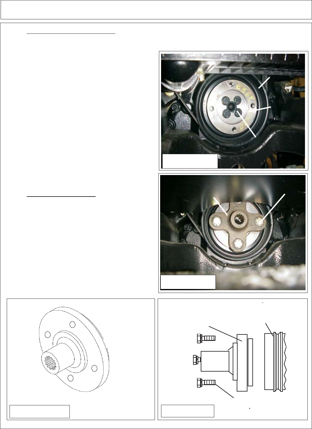
Pulley Adapter
P/N 02982837
Bolts & Lockwasher
(Qty 4 ea.)
CCCCCCCCC
CCCCCCCCC
Figure 13B
For JD-5225 & JD-5325 Shown
For JD-5225 & JD-5325 Shown