


© 2005 Alamo Group Inc.
Section 5 - 8
Switch Blade (JD-5105-5205-5225-5325-5425-5525, Asy. Man) 05/05
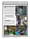
Figure 17
Figure 18
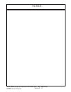
Cab
Model
Shown
Here
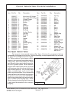
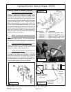
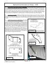
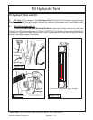
6. There are three holes in the handle
assembly that are used to stack the handles on
the control handle mount. Install the bolts through
the first handle, then the second handle and then
through the switch mount plate. Next the three
bolts are inserted through the handle mount. (See
Figure 17) This is for the cab model (or with
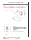
remote cable control. The Rops model the valve
is mounted to the valve stand and the control
handles are connected directly to the valve (See
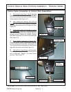
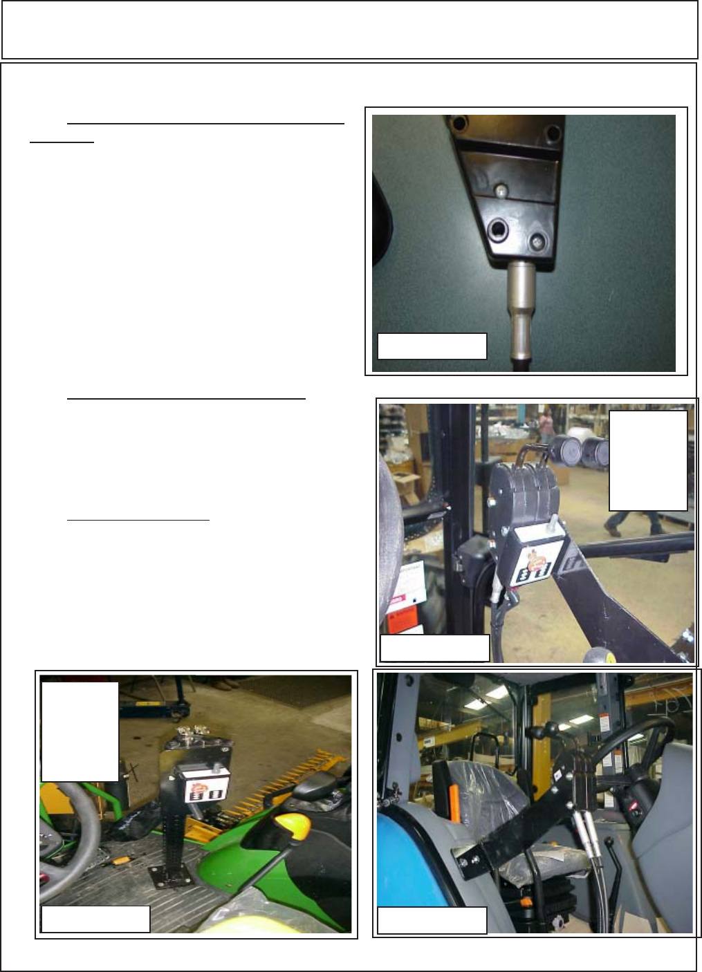
Figure 18). NOTE: Cab models the control
handles are installed with the three mounting bolt
heads toward operator and the nuts toward the
RH Door away from operator (See Figure 20)
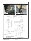
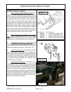
7. Install the Operation instruction decal to the
valve controls as shown (See Figure 18 & 19)
Push / Pull & Reversing Toggle
Switch:
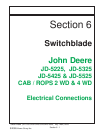
1. The push pull switch mount to the valve
stand on non cab tractors (See Figure 19) and
to the remote valve control cable handle mount
on a cab model (See Figure 18) . On Cab models
the switch can be mounted some where else if
that is what the customer wanted, however it is
recommended that the switch be mounted as
shown (See Figure 18 & 19)
Figure 20
Control Valve & Valve Controls Installation - Remote Cables
ROPS
Model
Shown
Here
Figure 19