


© 2005 Alamo Group Inc.
Section 7 - 6
Switch Blade (JD-5105-5205-5225-5325-5425-5525, Asy. Man) 05/05
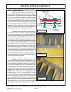
KNIFE BAR REPLACEMENT
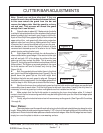
Knife Bar Replacement:
Replace the Knife Bar assembly will require the cutter bar assembly to be unbolted from skid
shoe / break-a-way assembly. Wear gloves as the knives on the cutter bar can be very sharp and can
cut you. (See Figure 10 & 11)
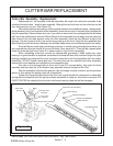
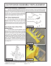
It will not be require to remove any of the hydraulic hoses or even take them loose. Looking down
at the planetary drive (and Hydraulic Pump Assembly) there are four nuts in the plate that is attached
to the drive assembly. Remove these four nuts, if you want to remove the four carriage bolts the skid
shoe will have to unbolted and removed. When lifting the drive assembly up and away from the cutter
bar take notice of the four tube spacers under the drive assembly, there are two different length of the
spacers. The short ones go to the rear and the long ones go to the front. Once the drive assembly has
been lifted off you will see a nylon bearing in the knife bar head clamp, it should have stayed in the clamp.
There will be two more bolts connecting cutter bar to break-a-way assembly once these nuts
are removed the cutter bar should lift up over the bolts if they were left in. There will be a square plate
under the cutter bar that has 6 holes in it, make certain to note this for reassembly.
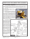
Use caution the knife bar can be very sharp, it is recommended that you wear gloves to protect
your hands. The Knife Bar will slide out at the drive end, if it will not slide out then something is wrong.
Check the rock guards, clips and other components to see where it is to tight. The easiest way if any
of these make it to tight is to unbolt them and remove them for now. The new or repaired knife bar will
install the same way, it will slide in from the drive end under clips and between rock guards. DO NOT
use hammer or force to install knife bar, if it will not slide in find out why because if the bar is forced in
it will be damaged or other component will be damages. The Knife bar and cutter bar can not operate
fitting tightly together they will bind causing damage..
When reinstalling cutter bar reverse the disassembly procedures. Make certain the nylon
bearing is in good condition or replaced, sometimes the clamp will have to be loosened to get the nylon
bushing installed into clamp and the drive stud that is attached to the drive assembly with two socket
head bolts, DO NOT tighten the clamp bolt at this time. This drive stud can be unbolted from drive
assembly, inserted into nylon bearing and re-bolted to drive assembly later (See Figure 10 & 11). if the
drive stud is removed from the drive assembly when you reinstall it the two socket head bolts will need
to be torqued to 35 ft. lbs.
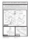
The nuts on the carriage bolts (4 short and 2 long 3/4" carriage bolts) that retain the drive
assembly and the cutter bar to the break-a-
way assembly must be torqued to 85 ft. lbs.
Tighten the clamp bolt around the
drive stud, use a good thread lock com-
pound on clamp bolt and tighten the clamp
bolt until the up & and down movement of
clamp on drive stud is removed. DO OVER
TIGHTEN the clamp bolt as the drive stud
has a bearing inside that will be damaged.
After the assembly is finished the
guards, clips and ledger must be checked
for clearance, see the previous section in
this manual for setting knife bar to cutter bar
components (See Figure 10 & 11).
The skid shoe will be the last item
reinstalled. Make certain the rod deflector
which bolts to the front of the skid shoe is
pointed correctly.
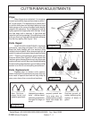
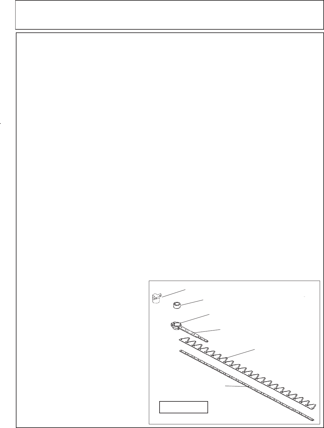
Drive Stud
Nylon Bearing
Clamp & Clamp Bolt
Knife Head Weldment
Blade Section
Knife Backing Strip
Figure 11