


MAINTENANCE
MAVERICK 03/09 Maintenance Section 4-21
© 2009 Alamo Group Inc.
MAINTENANCE
Spindle Service Procedure 02960553B and 02960553C
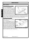
1. Remove blade bar or pan.
2. Remove hydraulic motor.
3. Remove spindle assembly from mower deck.
4. Drain remaining lubricant from housing.
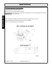
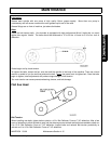
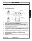
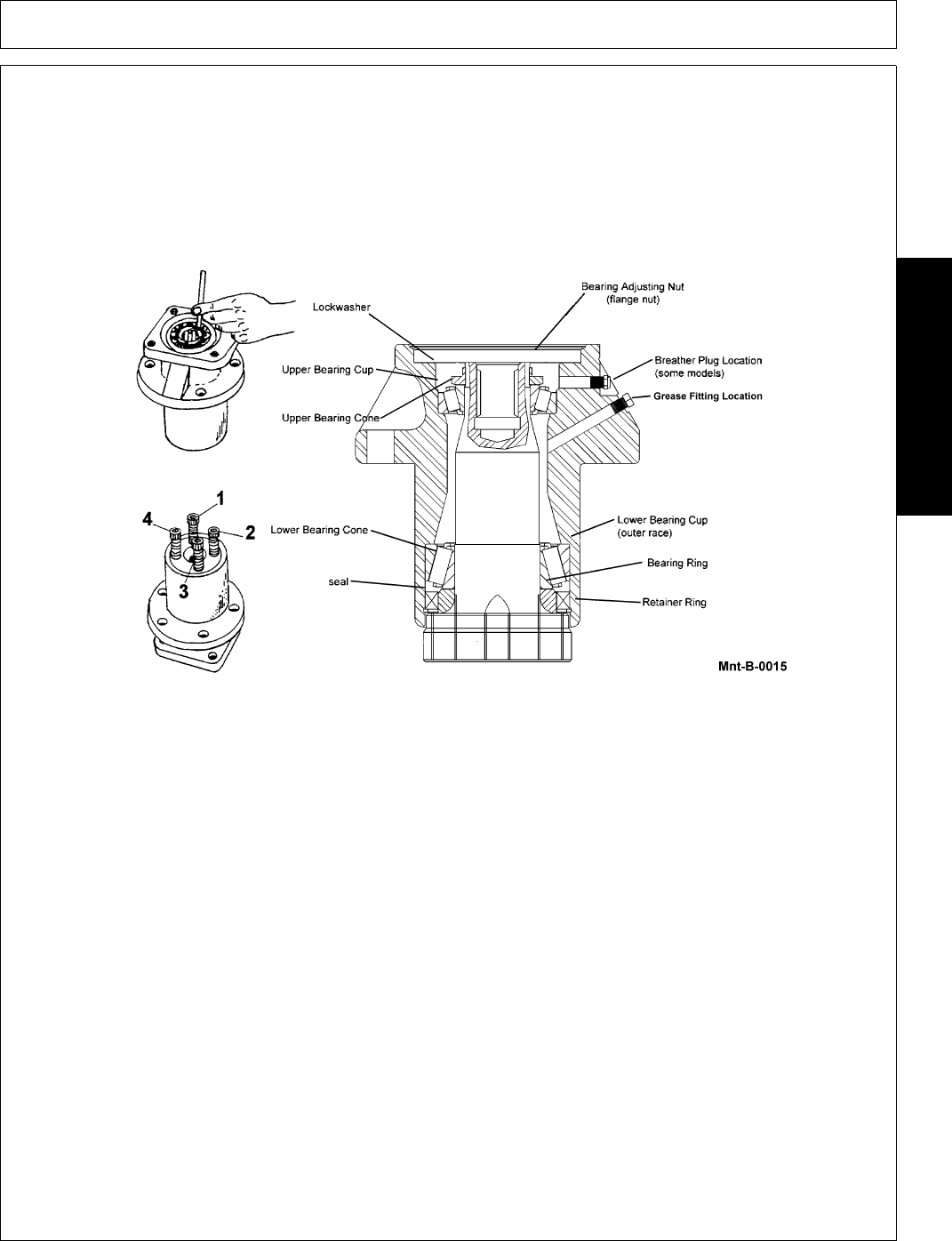
5. Using a 3/16" cape chisel, bend out the staking indentations on each side of the bearing adjusting nut.
To do this, place the chisel in the groove and parallel to the shaft. Drive the chisel downward until the
indentation is free of the shaft and threads (see Figure Mnt-B-0015).
6. Using the same chisel, straighten the tang on the lockwasher (if equipped with a lockwasher). NOTE:
The lockwasher will not be installed during assembly if the spindle uses the staked adjusting nut.
7. Remove bearing adjusting nut and lockwasher (if equipped). Discard these parts. They are not re-
usable. Install a new adjusting nut when assembling.
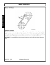
8. Screw the original blade bar bolts into the flange of the spindle shaft until they contact the bearing ring
(see Figure Mnt-B-0015).
9. In a clockwise pattern, rotate each bolt 1/4 turn (see Figure Mnt-B-0015). Continue turning the bolts
1/4 turn at a time (maximum of 3 turns), until the special shank bolts (P/N 02964353) will thread into
the spindle.
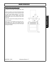
10. Remove the original bolts and replace them with the shank bolts. Screw the shank bolts in until they
contact the bearing ring.
11. In a clockwise pattern, rotate the bolts 1/4 turn at a time until the spindle is free from the housing.
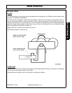
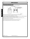
12. Remove the seal retaining ring from the housing using a flat screwdriver or similar tool.
13. Remove the seal and bearing.
14. A punch or similar tool can be used to remove the bearing cups from the housing if the cups are not to
be re-used.