OPERATION
MAVERICK 3/09 Operation Section 3-26
© 2009 Alamo Group Inc.
OPERATION
6.4 The Instrumentation
Your Maverick Boom utilizes instrumentation for certain decision-making activities. Listed below are the
sensors included on this unit
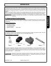
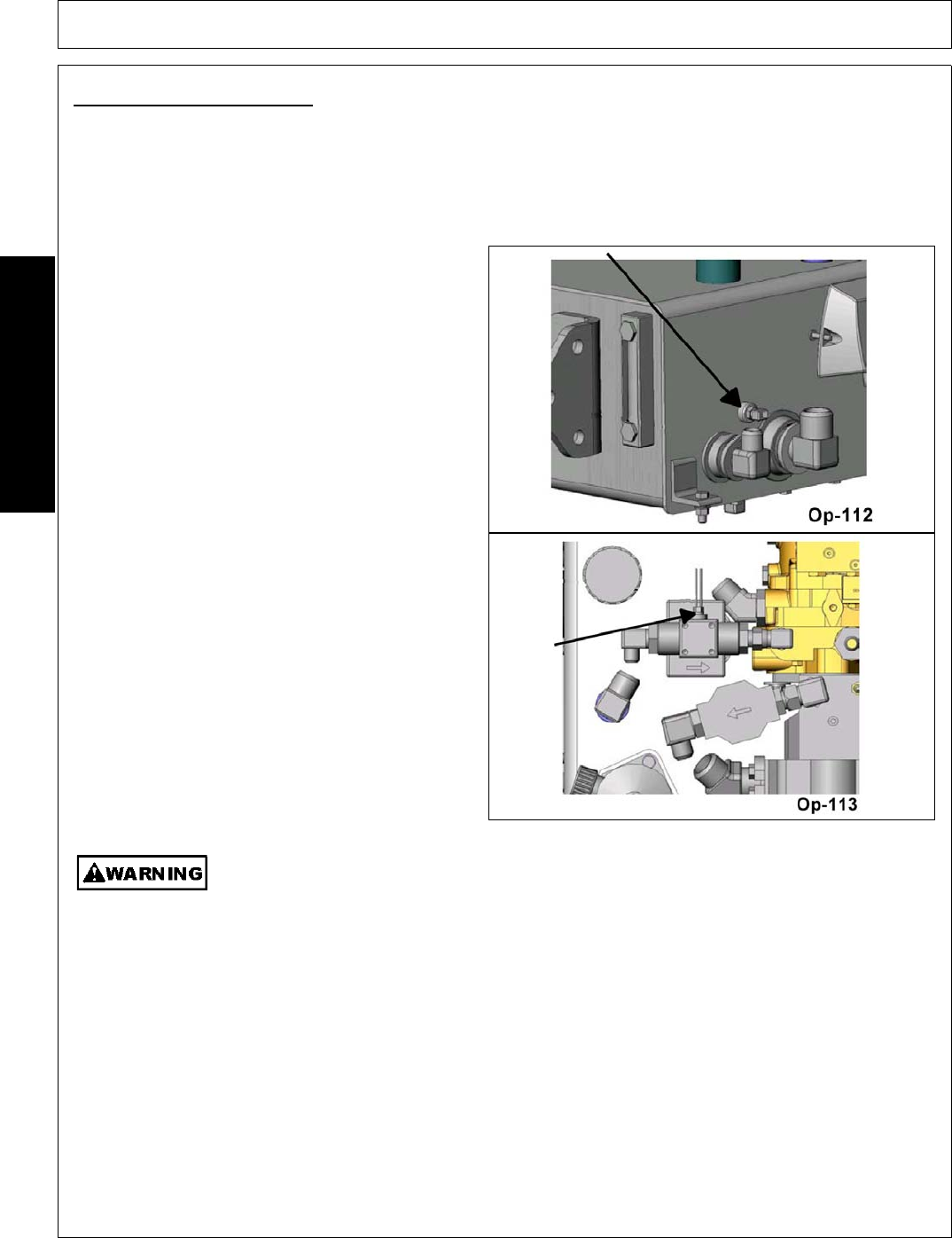
• Tank Temperature sensor
• Charge pressure filter switch
• Valve pressure filter switch
• Return filter switch.
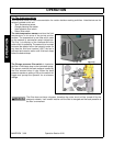
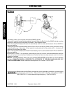
The tank temperature sensor monitors the fluid
temperature in the area of the pump suction
screens. The temperature is real time and is used
on the network to accomplish certain objectives.
The first, is to display on the interface while the
cutter-circuit is operating. The second is to be used
to control the electric fan on the hydraulic cooler. At
any time the fluid level reaches 150°F the fan is
activated and remains active until fluid level drops
below the desired temp.
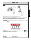
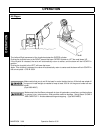
The Charge pressure filter switch is located at
the filter in the charge loop on the hydrostatic pump.
The sensor monitors the back-pressure created by
the filter element when in use. When the back
pressure reaches a setting of 50 psi the switch will
trigger and prompt the operator for an element
change.
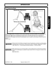
The filter does not have a bypass, therefore the cutter circuit will be turned off by the
electronic network. It will remain inactive until the filter is changed and the back-pressure at
the filter is normalized.


