


OPERATION
MAVERICK 3/09 Operation Section 3-27
© 2009 Alamo Group Inc.
OPERATION
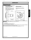
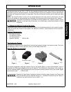
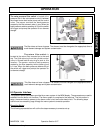
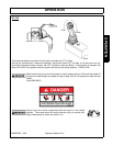
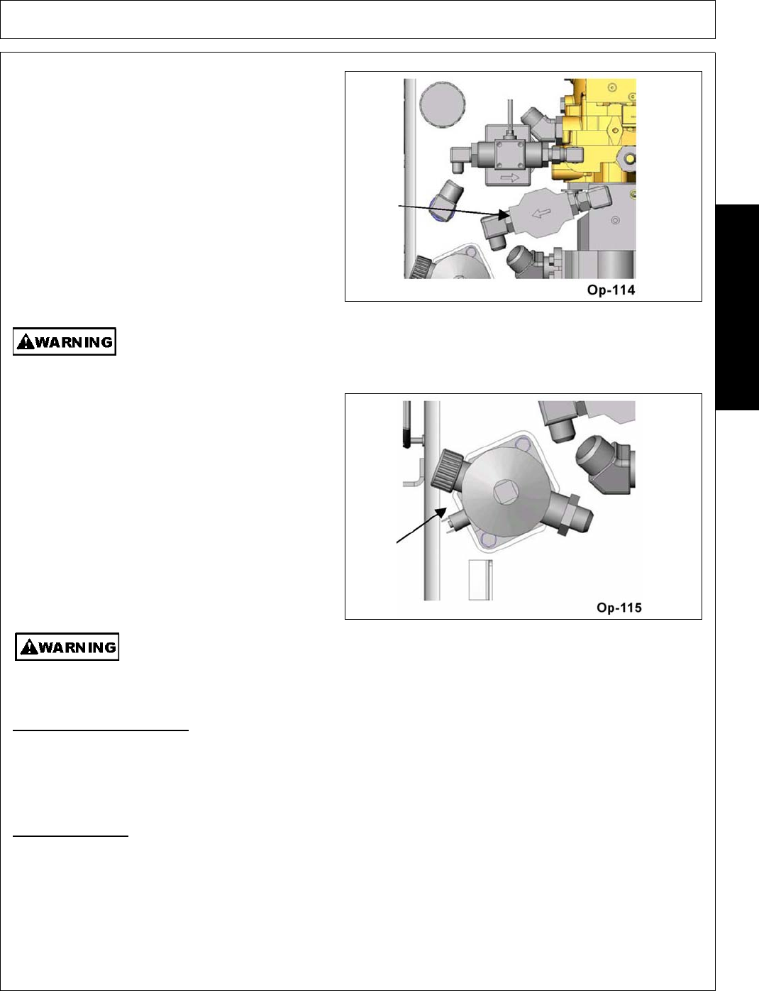
The valve pressure filter switch is located at the
pressure filter in the valve pressure circuit, between
the closed center load sense pump and the control
valve. The sensor monitors the back-pressure
created by the filter element when in use. When the
back-pressure reaches a setting of 50 psi the switch
will trigger and prompt the operator for an element
change.
The filter does not have a bypass. The element must be changed at the appropriate time to
avoid element damage and system contamination.
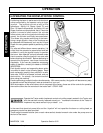
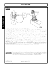
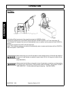
The return filter switch is
located at the return filter mounted on to the tank
top. The fluid returning from the cylinder control
valve is filtered before returning to tank at this
location. The sensor monitors back-pressure
created by the filter assembly while cylinder circuit
is in use. When the back-pressure reaches 25 psi
the switch will trigger and prompt the operator for
an element change.
This filter does not have a bypass. The element must be changed at the appropriate time to
avoid element damage and system contamination.
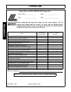
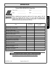
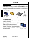
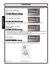
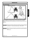
6.5 Operator Interface
The operator selects parameters provided by a menu system in the MDM display. The parameters are used to
establish how the boom unit functions. The menu system is comprised of two sections. The first section is
setup, the second section powers up the boom control circuit and cutter-head circuit. The following steps
outline how to successfully page through the menu system to execute operation.
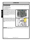
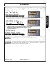
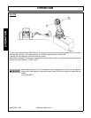
Executing Set-up
The following representations will outline the steps necessary to execute set-up.