


OPERATION
MAVERICK 3/09 Operation Section 3-24
© 2009 Alamo Group Inc.
OPERATION
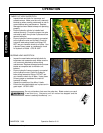
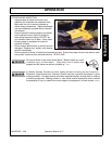
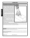
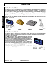
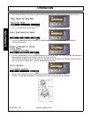
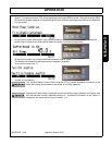
6.2 The Mower Head Circuit
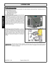
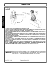
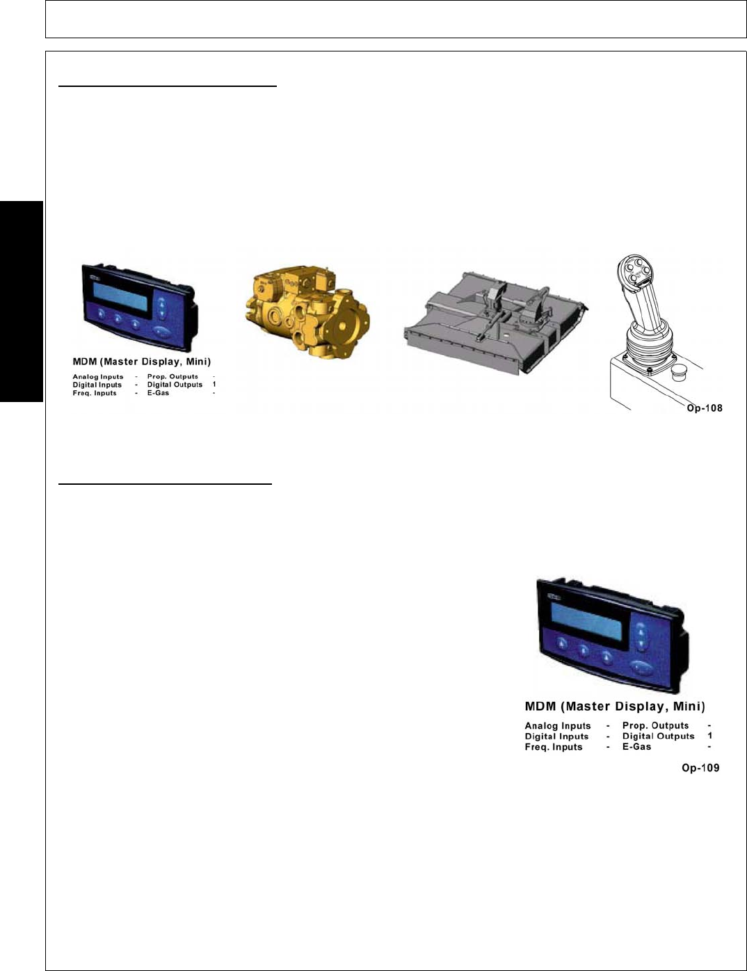
The Motor circuit used for the cutting operation is operated through the Operator display (fig 1). By selecting
the activation parameter the coil will shift the servo-piston at the hydrostatic pump (fig 2), stroking the pump
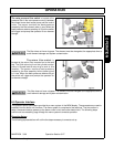
into the ON position. Flow will then be supplied to the hydraulic motor at the cutter-head (fig 3). Activate the
motor circuit while the engine RPM is at idle. Once activated, the engine RPM can be raised to the 540 PTO
speed. If the 540 PTO is not noted on the RPM gauge of your tractor consult the owner’s manual to find the
540 PTO speed
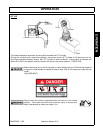
At any time the E-stop (fig 4) will deactivate the cutter circuit, and the blade will stop within six seconds upon
required. OPS-B- 0047
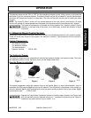
Figure 1 Figure 2 Figure 3 Figure 4
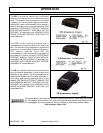
6.3 The Electronic Network
The electronic network is the control and communication network that receives and transmits data to certain
components in the boom control system. It’s purpose, is to manage the incoming and outgoing information.
There are five main components:
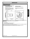
The MDM is an Operator Display that is located in the cab. The purpose
of the display is to house the programming software for system control,
and provide an interface between the operator and the Maverick boom.
The interface is utilized through a multi-screen function that allows the
operator to set individual parameters for customized control.
The display also provides tools such as an on-board measurement
device, useful for determining short circuits, component loss, and/or
power supply issues. REFERENCE PRODUCT MANUAL FOR MDM
DISPLAY. AVAILABLE ON THE INTERNET AT www.iqan.com.
VIEWABLE WITH ABOBE ACROBAT READER, AVAILABLE AT
www.adobe.com. OPS-B- 0048