


ASSEMBLY
A84B 03/07 Assembly Section 3-6
© 2007 Alamo Group Inc.
ASSEMBLY
PULL-TYPE
The standard Pull-Type unit will be shipped from the factory in the following bundles: 1) Basic Assembly,
2)Jackshaft Assembly, 3) Jackshaft Bearing Support, 4) Gearbox Protective Shield, 5) PTO Driveline, 6)
Tongue Assembly, 7) Control Rod Bundle, 8) Axle Arm Bundle and Lift Lug and/or Spring Assembly, 9) Wheels,
10) Jack, 11) Operator’s Manual and Flat Blades. Other optional bundles that may be shipped with your unit:
Ratchet Lift Screw or Hydraulic Cylinder with Hydraulic Hose and Hose Bracket, Puncture-Proof tires or 14" or
15" Wheels, Chain Guards. Extra Equipment items include: Chain Guards, Solid Guards, Dual Wheels, Hitch
and Spring Assembly (Axle).
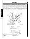
The Components of these machines are quite heavy. Block all components up securely
before working under or putting extremities under such parts.
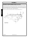
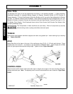
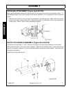
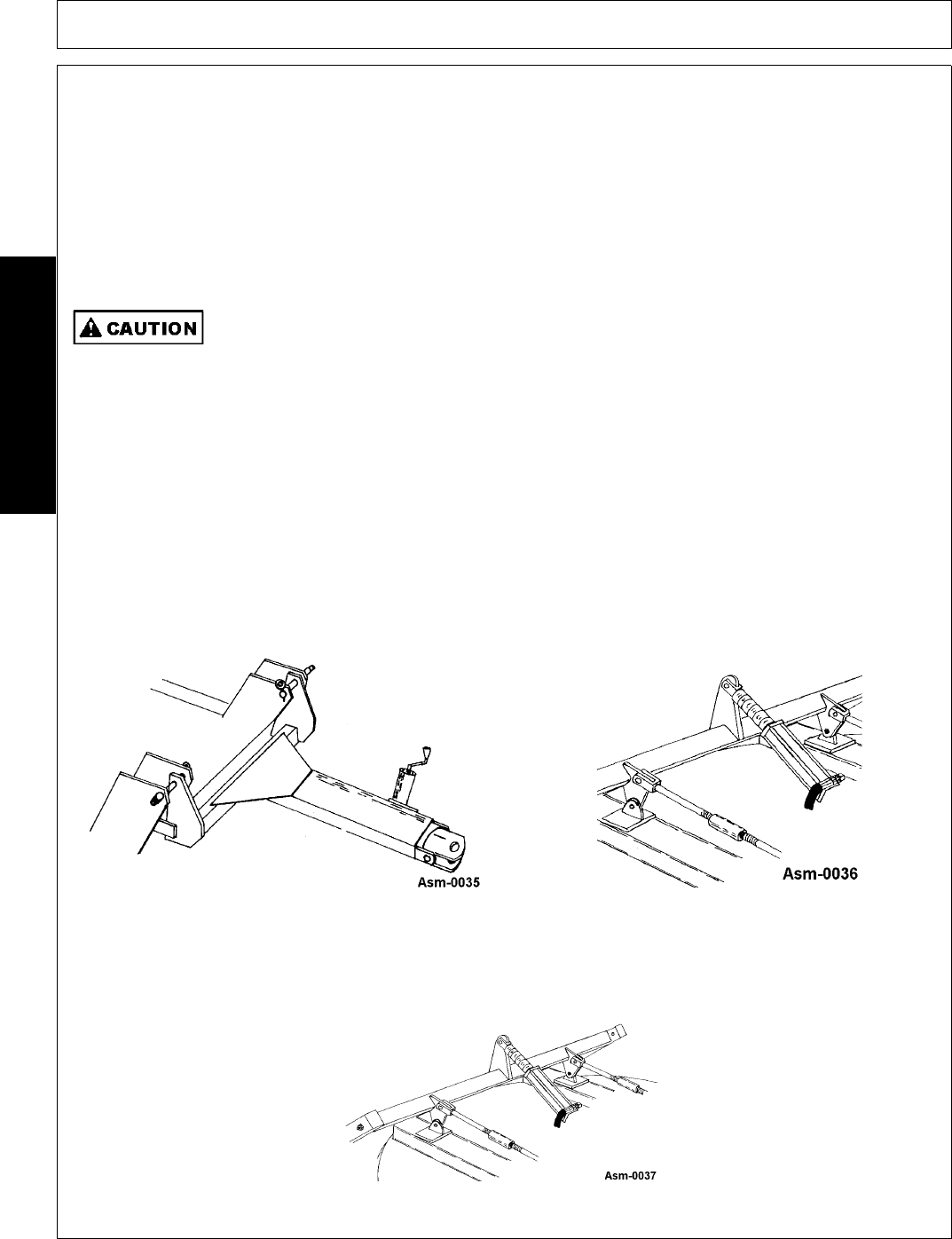
TONGUE
Insert tongue lugs between mainframe uprights and retain using special pin. Insert retaining clip to retaining
pin. Figure Asm-0035.
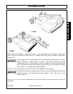
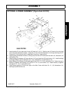
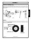
AXLE
Attach Rear Axle to the lugs on the rear of the mainframe using (5) 3/4 x 3-1/2 bolts and locknuts. Figure
6.Install bolts (10) & nuts (11 - not shown) on top and bottom of tailwheel beam. Insert through pair of holes
which will give approximate desired cutting height. Tighten all bolts. Figure Asm-0036.
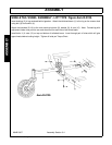
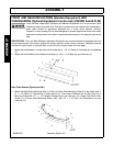
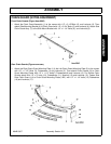
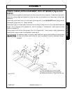
CONTROL RODS
Attach the two level-lift control rods to the lower lugs on tongue and to lugs on the rear axle tube using pins,
washers and cotter pins. Note: The adjusting nuts on control rods should be to rear of machine. Figure Asm-
R-0037.