


ASSEMBLY
A84B 03/07 Assembly Section 3-2
© 2007 Alamo Group Inc.
ASSEMBLY
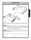
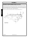
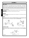
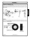
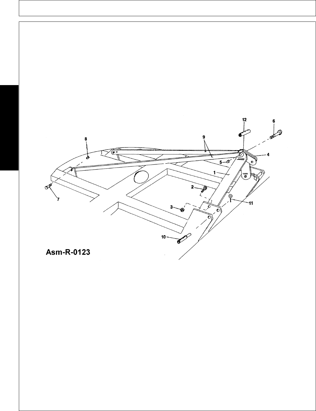
STANDARD A-FRAME ASSEMBLY(FIGURE Asm-R-0123)
Attach right and left A-frame's (1) to the A-frame lugs on Mower deck with two 5/8 x 2 bolts (2) and locknuts (3).
Place Top Link (4) and Bushing (12) between right and left A-frame's (1). Attach long Braces (9) to the outside
of short A-frame Braces (1) with one 3/4 x 6 bolt (6) and locknut (5). NOTE: Top Link (4) must be free to pivot
for the mower to operate properly. The long A-frame brace members (9) attach to lugs on rear of Mower Deck
with two 5/8 x 1-1/2 bolts (7) and locknuts (8). Tighten all bolts securely
Attach the Cat. II Hitch pins (10) to the top front holes in the lift lugs and retain with pins (11).