


Installation
53
F8208301
© Copyright, Alliance Laundry Systems LLC – DO NOT COPY or TRANSMIT
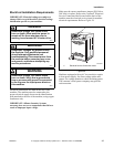
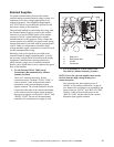
External Supplies
For proper communication between the washer-
extractor and an external chemical supply system, it is
important for the low-voltage signal power to be
connected properly. The included wiring diagram
(F8133502) shows several different options for safe
and correct wiring of this interface.
The preferred method for connecting the wiring from
the external chemical supply system to the washer-
extractor is to use the 300mA power of the washer-
extractor’s 24VAC control transformer, which is
intended strictly for this purpose. Other voltage and
current options are available, but require some wiring
changes and must be provided with an external power
source. Under no circumstances should the high-
voltage machine supply connections or source be used
for the communication wiring.
Basically, wash-cycle signals are provided to the
external chemical supply equipment and a “wait for
the next step” signal can be received from the supply
equipment. Communication wiring connections,
which include a single row of identified terminal
blocks, can be found under a service panel at the upper
back of the machine.
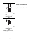
1. Use the Internal 24VAC 300 Control
Transformer (Recommended by Alliance
Laundry Systems)
There are 3 terminals necessary for this
connection option. Terminal “24VAC COM” is
used to connect 1 side of the internal control
transformer to the external dispenser input
signals common. The second terminal is used to
connect the other side of the control transformer
to the washer-extractor output signals common
through a red jumper wire between “24VAC” and
“RELAY COM”. Do not use the transformer
terminals if an external power supply is used.
2. Use an External AC Power Source (Not
Provided by Alliance Laundry Systems)
NOTE: Power for external supplies must not be
derived from the high-voltage main power
connection point.
The external power must supply power of
240VAC or less and be protected at 3 Amps or
less. Remove the red jumper wire installed by the
factory between “24VAC” and “RELAY COM”.
Connect 1 side of the external power to the
“RELAY COM” and the other to the external
dispenser input signals common.
CHM2336N
1 Relay Com
2 Red Jumper Wire
3 24 VAC
4 Transformer
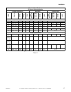
EXTERNAL DISPENSER CONNECTIONS
RELAY COM
RELAY
COM
Supply 1
External
Dispensing
System
Internal
Supply
300mA Max
24VAC COM
24VAC COM
JUMPER FOR INTERNAL
24 VAC SUPPLY
CONNECTED TO RELAY
COM. (REMOVE IF NOT
WIRING TO INTERNAL
24 VAC SUPPLY
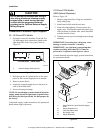
STEP 1: Insert screwdriver & press down
to open cage clamp.
STEP 2: Insert Wire
8.5mm
Strip Length
Wire Size 28-16AWG
0.08-1.5mm
24VAC
RED
ES 1
ES 2
ES 3
ES 4
EXAMPLE FOR EXTERNAL
DISPENSER CONNECTION
CHM2336N
2
4
1
3