


Installation
27
F8208301
© Copyright, Alliance Laundry Systems LLC – DO NOT COPY or TRANSMIT
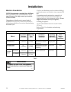
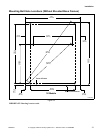
Machine Anchoring
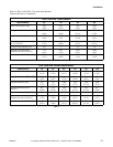
Before anchoring the machine, refer to Table 1 to
determine the appropriate method of anchoring for the
machine.
NOTE: Improper installation may void the
warranty. Consult the manufacturer or distributor
before varying from a procedure.
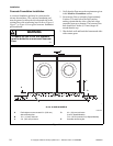
Direct-to-Finished-Floor Installation
Installing With Expansion Bolts for
2 Speed Models
NOTE: Expansion bolts are not suitable for
variable-speed machine installations.
1. Verify the floor meets the requirements given in
the Machine Foundation section.
2. Mounting surface should be level and machine
must be properly grouted.
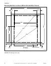
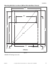
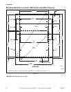
3. Use the base of the machine as a template by
positioning the machine in the desired location
and marking the pre-drilled mounting holes on
the floor. Mounting Bolt templates are available
through Alliance Laundry Systems.
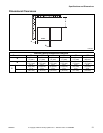
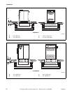
4. Refer to Figure 9 and Table 4 to set the drill
depth gauge.
5. Drill the holes to the set depth. Refer to Table 4.
6. Use compressed air or a squeeze bulb to clean out
debris from each hole.
7. Fill half the hole depth with an industry-accepted
adhesive anchoring system.
8. Insert expansion bolt until it reaches the bottom
of the hole and 1.5 inches (38 mm) of the bolt
extends above the surface.
9. Allow adhesive around bolt to cure properly.
NOTE: Select the proper size and strength anchor
system. Follow the manufacturer’s installation
instructions and recommended cure times.
10. Position machine over anchoring bolts.
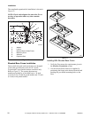
11. Raise and level the machine .5 inch (13 mm) off
the floor on three points, using spacers such as
nut fasteners.
12. Fill the space between the machine base and the
floor with a good quality non-shrinking
machinery grout to ensure a stable installation.
Grout completely under all frame members.
13. Position washers and nuts on bolts and finger
tighten nuts to machine base.
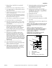
14. Before grout sets completely, make a drain
opening in the grouting at the rear center of the
machine with a stiff piece of wire. This opening
should be approximately .5 inch (13 mm) wide to
allow any surface water build-up under the base
of the machine to drain away. Do not omit this
step.
15. Allow machine grout to set, but not cure.
16. Remove the spacers carefully, allowing the
machine to settle into the grout.
17. Tighten the nuts by even increments – one after
the other using the specified torque – until all are
tightened evenly and the machine is fastened
securely to the floor. Refer to Table 4.
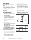
Figure 9
CHM2285N
Anchor Specifications
(refer to Figure 9)
Torque
(ft.-lbs.)
Models A
B
(minimum)
C
20-60 5/8
in.
2.75 in.
(69.9 mm)
.625 in.
(15.9 mm)
90
(ft.-lbs.)
80-125 3/4
in.
3.25 in.
(82.6 mm)
.75 in.
(19 mm)
175
(ft.-lbs.)
Table 4
CHM
B
C
A