


Installation
29
F8208301
© Copyright, Alliance Laundry Systems LLC – DO NOT COPY or TRANSMIT
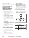
3. Refer to Figure 9 and Table 4 to set the drill
depth gauge.
4. Drill the holes to the set depth. Refer to Table 4.
5. Use compressed air or a squeeze bulb to remove
debris from each hole.
6. Fill half the hole depth with an industry accepted
adhesive anchoring system.
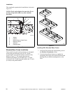
7. Insert bolt until it reaches the bottom of the hole
and 1.5 inches (38 mm) of the bolt extends above
the base frame. Refer to Figure 10.
8. Allow adhesive around the bolt to cure properly.
9. Position base frame over anchoring bolts.
10. Raise and level the base frame .5 inch (13 mm)
off the floor on three points, using spacers such
as nut fasteners.
11. Fill the space between the base frame and the
floor with a good quality non-shrinking
machinery grout to ensure a stable installation.
Grout completely under all frame members.
12. Position washers and locknuts on bolts and finger
tighten nuts to base frame.
13. Before grout sets completely, make a drain
opening in the grouting at the rear of the base
frame with a stiff piece of wire. This opening
should be approximately .5 inch (13 mm) wide to
allow any surface water build-up under the base
of the machine to drain away. This drain opening
must not be near frame mounting bolts. Do not
omit this step.
14. Allow machine grout to set, but not cure.
15. Remove the spacers carefully, allowing the base
frame to settle into the wet grout.
16. Tighten nuts by even increments – one after the
other using the specified torque – until all are
tightened evenly and the base frame is fastened
securely to the floor. Refer to Table 4.
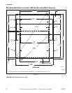
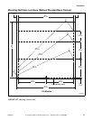
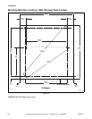
17. Position the machine over the base frame, aligning
the mounting holes on the machine with the
corresponding holes on the frame.
18. Install a bolt, lockwasher, and nut in each
mounting hole. Use 5/8 inch – 18 x 2.00 grade 5
mounting bolts with 5/8 inch – 18 grade B nuts
and 5/8 inch lockwashers.
19. Hand tighten each nut.
20. Tighten the two rear nuts two turns.
21. Tighten the two front nuts two turns.
22. On 30, 40 and 60 models, tighten the two middle
nuts firmly.
23. Tighten the two front nuts firmly; tighten the two
rear nuts firmly.
NOTE: Check and retighten the locknuts after five
to ten days of operation and every three months
thereafter.
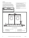
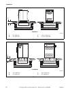
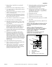
NOTE: For 80 and 125 pound models, a
bolt-locator fixture or rebar frame is available as
an option. This is designed to be embedded in
concrete. Refer to Figure 12.
IMPORTANT: Do not install any 80 or 125
machines on an elevated base frame.
Figure 12
P035I
1 Machine Base
2 Mounting Bolt Threads
3 Grouting
4 Bolt-Locator Fixture or Rebar Frame
1
2
3
4