


9
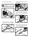
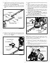
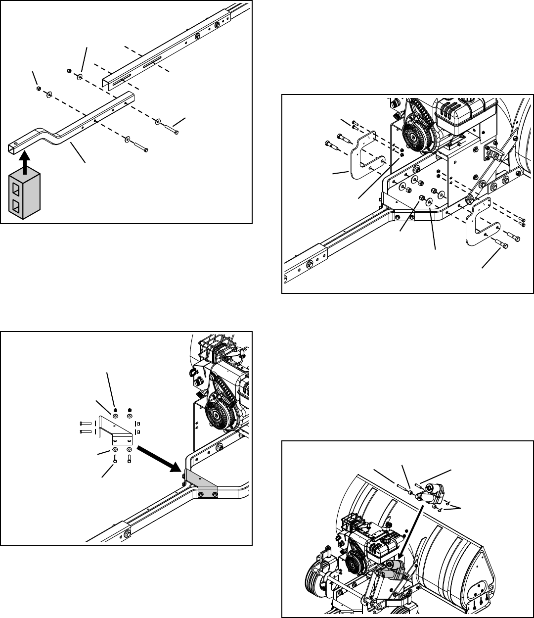
FIGURE 18
Attach the support bracket to the mounting tubes using 18.
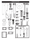
(4) 5/16" x 1-3/4" hex bolts, (8) 5/16" washers and (4)
5/16" nylock nuts. Tighten.
5/16" NYLOCK NUT
5/16" WASHER
5/16" x 1-3/4"
HEX BOLT
5/16" WASHER
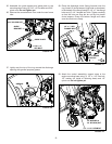
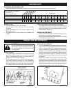
FIGURE 15
Attach the bent rear frame tube to the push channel 16.
using (2) 1/2" x 3-1/2" hex bolts, (4) 1/2" washers and
(2) 1/2" nylock nuts. Do not tighten yet.
Remove the concrete block from under the engine 17.
and place it underneath the the end of the rear frame
tube.
1/2" NYLOCK
NUT
1/2" WASHER
1/2" x 3-1/2"
HEX BOLT
REAR FRAME TUBE
1/2" x 3"
CLEVIS PIN
.5" x 1" x .59"
SPACERS (2)
1/2" x 2"
CLEVIS PIN
HAIRPINS (2)
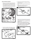
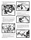
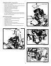
FIGURE 17
NOTE: Before proceeding with next assembly step, make
sure the actuator is fully extended. Refer to step 11 on
page 6 in the Wiring Assembly Section.
Fasten top of actuator to wheel assembly using (1) 23.
1/2" x 3" clevis pin, (2) .5" x 1" x .59" spacers and (1)
hairpin.
Fasten bottom of actuator to actuator bracket using (1) 24.
1/2" x 2" clevis pin and (1) hair pin.
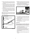
Place the wheel assembly behind the engine mounting 19.
base.
Fasten the bottom of the anchor brackets (part of 20.
wheel assembly) to the outside of the mounting tubes
using (4) 1/2" x 2-1/4" hex bolts, (4) 1/2" washers (on
inside of mounting tube) and (4) 1/2" nylock nuts. Do
not tighten yet.
Fasten the tops of the anchor brackets to the engine 21.
mounting base using (4) 5/16" x 1" hex bolts and (4)
5/16" nylock nuts. Do not tighten yet.
Tighten22. all nuts and bolts assembled in steps 12-
14 and 18-21. Do not tighten the nuts and bolts
assembled in steps 15-16 at this time.
NOTE: Complete wheel assembly not shown for clarity.
5/16" x 1"
HEX BOLT
1/2" NYLOCK
NUT
1/2" WASHER
1/2" x 2-1/4"
HEX BOLT
5/16" NYLOCK
NUT
ANCHOR
BRACKET
FIGURE 16