


11
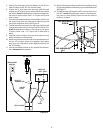
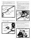
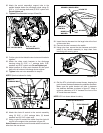
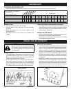
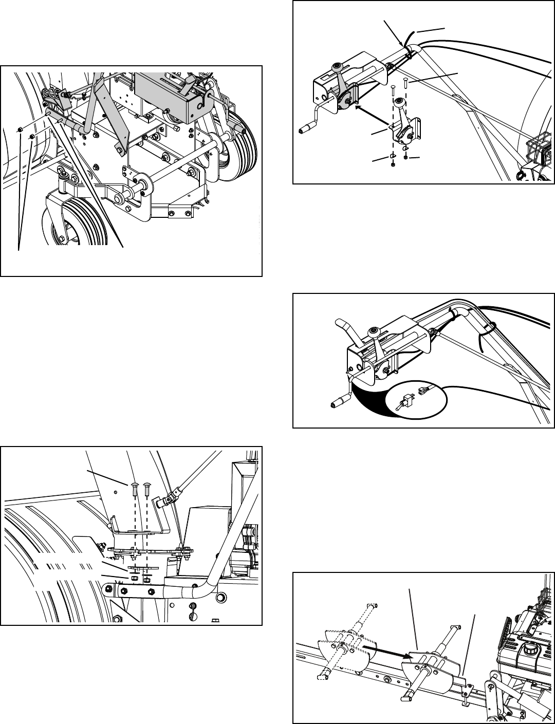
Attach the chute tilt control to the control assembly 36.
using (2) 5/16" x 1-3/4" carriage bolts, (2) bowed
washers and (2) 5/16" nylock nuts.
Using a nylon tie, secure the cables from the chute tilt 37.
control to the support tube as shown in gure 25.
Note: Do not secure the chute tilt control cables in locations
other than the one shown.
SECURE CABLES HERE
NYLON TIE
BOWED
WASHER
CHUTE TILT
CONTROL
5/16" NYLOCK
NUT
5/16" x 1-3/4"
CARRIAGE BOLT
FIGURE 24
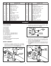
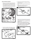
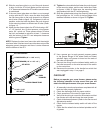
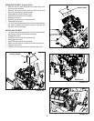
Cut the nylon tie that holds the two chute crank brackets 32.
together.
Attach the chute crank brackets to the discharge 33.
housing using (2) 5/16" x 1" carriage bolts, 5/16"
washers and 5/16" nylock nuts. Do not tighten yet.
Adjust position of chute crank brackets so that spiral 34.
does not rub bottom of discharge chute notches.
Tighten35. bolts and nuts assembled in step 33.
NOTE: Spiral not shown for clarity.
FIGURE 23
5/16" x 1"
CARRIAGE BOLT
5/16" WASHER
5/16" NYLOCK
NUT
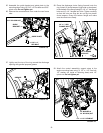
Roll the ATV up behind the snow thrower, keeping the 41.
push channel centered between the stabilizer brackets.
Make sure the guide bracket will slide in between
the stabilizer brackets as shown in gure 27. Keep a
minimum clearance of 3"-4" between the front of the
ATV and the snow thrower.
NOTE: ATV not shown below for clarity.
FIGURE 26
Insert the wire harness into the large hole at the front 38.
of the control box.
Connect the wire harness to the switch.39.
Using nylon ties, secure the wire harness and clutch 40.
cable to the handle assembly to keep them from
interfering with moving parts.
FIGURE 25
STABILIZER BRACKETS
GUIDE BRACKET
5/16" x 1-1/4"
CARRIAGE BOLTS
5/16" NYLOCK NUTS
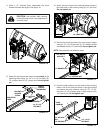
Attach the control assembly's support tube to the 30.
welded bracket below the discharge chute using (2)
5/16" x 1-1/4" carriage bolts and (2) 5/16" nylock nuts.
Do not tighten yet.
Tighten31. bolts assembled in steps 29 and 30.
FIGURE 27