


10
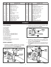
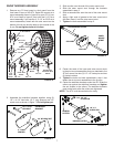
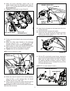
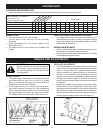
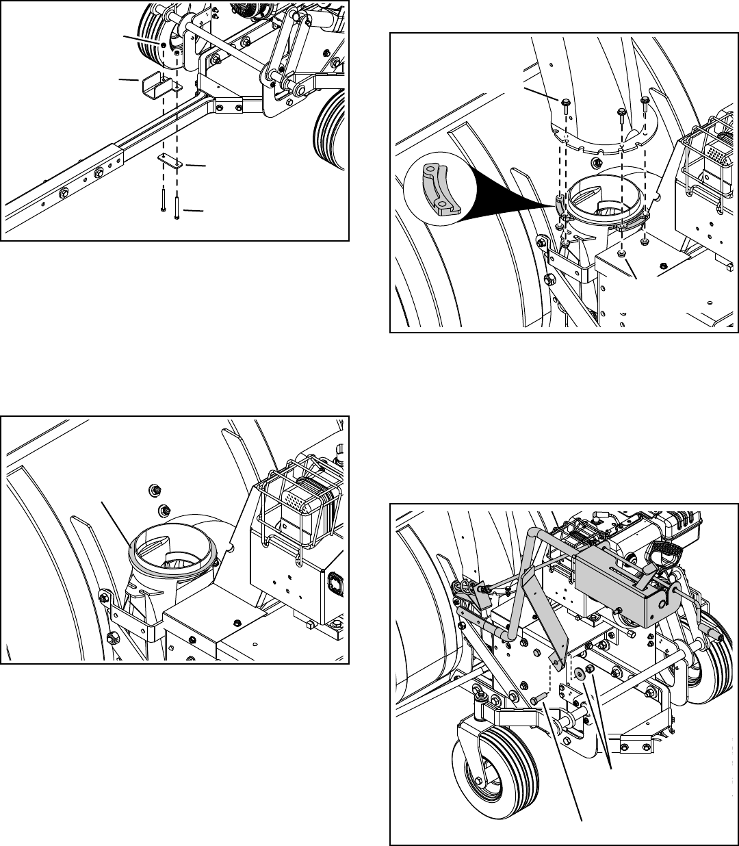
Lightly coat the top of the ring around the discharge 27.
opening with general purpose grease.
GREASE
FIGURE 20
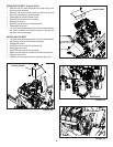
5/16" x 3"
HEX BOLT
5/16" NYLOCK NUT
GUIDE PLATE
GUIDE
BRACKET
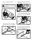
FIGURE 19
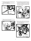
Assemble the guide bracket and guide plate to the 25.
mounting tubes using (2) 5/16" x 3" hex bolts and 5/16"
nylock nuts. Do not tighten yet.
Remove the concrete block from under the rear frame 26.
tube.
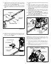
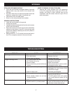
Attach the control assembly's support strap to the 29.
engine mounting base using (1) 1/2" x 1-1/2" hex bolt,
1/2" washer (on inside of mounting base) and 1/2"
nylock nut. Do not tighten yet.
FIGURE 22
1/2" x 1-1/2" HEX BOLT
1/2" WASHER &
1/2" NYLOCK NUT
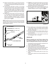
Place the discharge chute (facing forward) onto the 28.
ring. Attach (3) chute keepers (right side up as shown)
to the bottom of the ange using (6) 1/4" x 1" hex ange
bolts and (6) 1/4" anged lock nuts. Tighten carefully
so that the nuts are snug but do not dig into plastic
chute keepers. Grasp the bottom ange and make
sure the chute turns freely.
FIGURE 21
1/4" FLANGED
LOCK NUT
1/4" x 1" HEX
FLANGE BOLT