51
OPERATION/CONTROL
3
• Start signal.................................. Switch, relay, etc. (for 1)
• Frequency setting signal............. 0 to 5V, 0 to 10V or 4 to 20mA DC signals from a potentiometer or
outside the inverter (for 2)
• Operation unit............................. Operation panel (FR-DU04), parameter unit (FR-PU04)
• Connection cable........................ To be prepared for use of the operation unit away from the inverter
FR-CB2 (option) or the following connector and cable available on the
market:
Connector : RJ45 connector
Cable : Cable conforming to EIA568 (e.g. 10BASE-T cable)
3) Combined operation mode
Change the setting of Pr. 79 "operation mode selection" as follows:
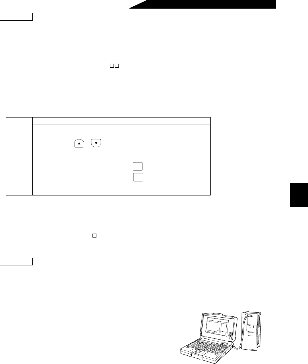
(4) Communication operation mode
Communication operation can be performed by connecting a personal computer and the PU connector with
the RS-485 communication cable.
The inverter setup software (FR-SW -SETUP-WE (or - WJ for Japanese Version)) is available as a start-up
support software package for the FR-A500.
• Connection cable........................ Connectors and cables available on the market
•Connector ...........................: RJ45 connector
•Cable ..................................: Cable conforming to EIA568
(e.g. 10BASE-T cable)
• For the operation enviroment of inverter setup software, refer to the instruction manual of the inverter
setup software.
Setting
Description
Running frequency setting Start signal
3
PU (FR-DU04/FR-PU04)
•Direct setting and / key
setting, Multi-speed setting
Terminal signal
•STF
•STR
4
Terminal signal
•0 to 5VDC across 2-5
•0 to 10VDC across 2-5
•4 to 20mADC across 4-5
•Multi-speed selection (Pr. 4 to Pr. 6, Pr. 24
to Pr. 27, Pr. 232 to Pr. 239)
•Jog frequency (Pr. 15)
Parameter unit
• key
• key
Preparation
FWD
REV
Preparation


