19
2
INSTALLATION AND WIRING
(3) Cables, crimping terminals, etc.
The following table lists the cables and crimping terminals used with the inputs (R, S, T) and outputs (U, V,
W) of the inverter and the torques for tightening the screws:
•
FR-A520-0.4K to 55K
•
FR-A540-0.4K to 55K
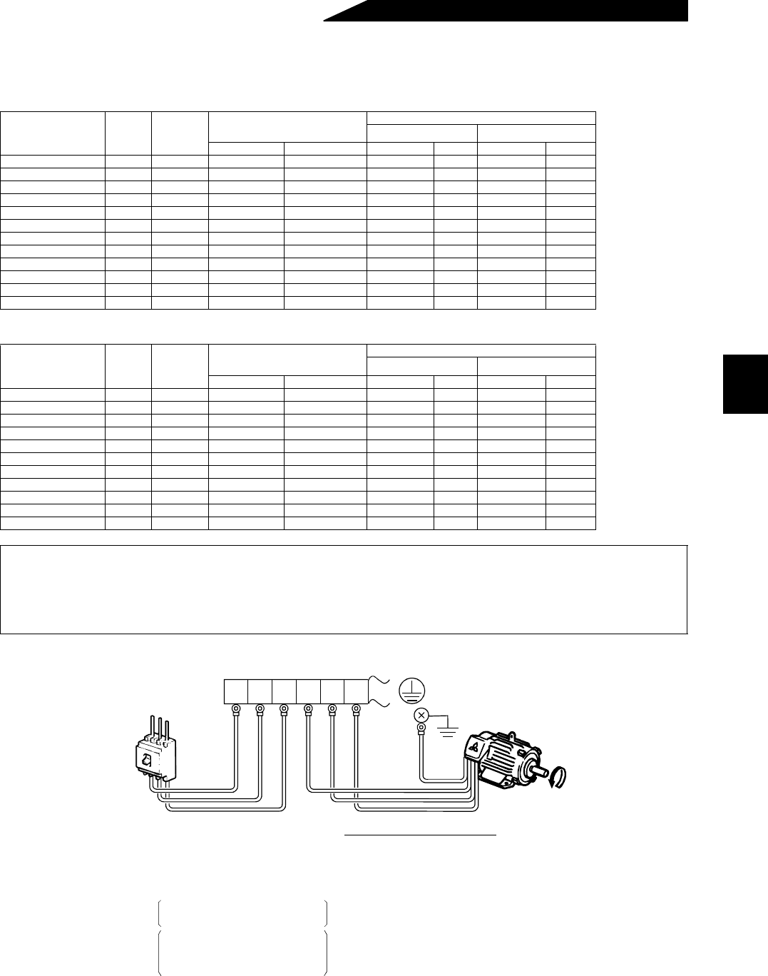
(4) Connection of the power supply and motor
Applicable Inverter
Type
Terminal
Screw
Size
Tightening
Torque
N⋅m
Crimping Terminals
HIV Cables (Note 1)
mm
2
AWG
R, S, T U, V, W R, S, T U, V, W R, S, T U, V, W
FR-A520-0.4K to 2.2K M4 1.5 2-4 2-4 2 2 14 14
FR-A520-3.7K M4 1.5 5.5-4 5.5-4 3.5 3.5 12 12
FR-A520-5.5K M5 2.5 5.5-5 5.5-5 5.5 5.5 10 10
FR-A520-7.5K M5 2.5 14-5 8-5 14 8 6 8
FR-A520-11K M5 2.5 14-5 14-5 14 14 6 6
FR-A520-15K M6 4.4 22-6 22-6 22 22 4 4
FR-A520-18.5K M8 7.8 38-8 38-8 38 38 2 2
FR-A520-22K M8 7.8 38-8 38-8 38 38 2 2
FR-A520-30K M8 7.8 60-8 60-8 60 60 1/0 1/0
FR-A520-37K M10 14.7 100-10 100-10 100 100 4/0 4/0
FR-A520-45K M10 14.7 100-10 100-10 100 100 4/0 4/0
FR-A520-55K M12 24.5 150-12 150-12 150 150 MCM300 MCM300
Applicable Inverter
Type
Terminal
Screw
Size
Tightening
Torque
N⋅m
Crimping Terminals
HIV Cables (Note 1)
mm
2
AWG
R, S, T U, V, W R, S, T U, V, W R, S, T U, V, W
FR-A540-0.4K to 3.7K M4 1.5 2-4 2-4 2 2 14 14
FR-A540-5.5K M4 1.5 5.5-4 2-4 3.5 2 12 14
FR-A540-7.5K M4 1.5 5.5-4 5.5-4 3.5 3.5 12 12
FR-A540-11K M6 4.4 5.5-6 5.5-6 5.5 5.5 10 10
FR-A540-15K M6 4.4 14-6 8-6 14 8 6 8
FR-A540-18.5K M6 4.4 14-6 8-6 14 8 6 8
FR-A540-22K M6 4.4 22-6 14-6 22 14 4 6
FR-A540-30K M6 4.4 22-6 22-6 22 22 4 4
FR-A540-37K M8 7.8 38-8 22-8 38 22 2 4
FR-A540-45K M8 7.8 38-8 38-8 38 38 2 2
FR-A540-55K M8 7.8 60-8 60-8 60 60 1/0 1/0
Note: 1. The cables used should be 75°C copper cables.
2. Tighten the terminal screws to the specified torques.
Undertightening can cause a short or misoperation.
Overtightening can cause the screws and unit to be damaged, resulting in a short or
misoperation.
Earth
(Ground)
Earth (Ground)
terminal
Power
supply
Motor
o-fuse
reaker
Connect the motor to U, V, W.
In the above connection,
turning on the forward rotation
switch (signal) rotates the motor
in the counterclockwise (arrow)
direction when viewed from
the load shaft.
The power supply cables
must be connected to R, S, T.
If they are connected to U, V,
W, the inverter will be damaged.
Phase sequence need not be
matched.
For use with a single-phase
power supply,the power supply
cables must be connected to
R and S.
RST
RST


