42
•••••••••••••••••••••••••••••••••••••••••••••••••••••••••••••••••••••••••••••••••••••••••••••••••••••••••••••••••••••••••••••••••••••••••••
<MPX DISPLAY SETTINGS> (continued)
■ MPX DISPLAY SETTINGS
Multiplexer setting of the <OUTPUT A> and <OUTPUT B>
are referenced below.
■ SPLIT/SEQUENCE
SPLIT/SEQUENCE allows selection of display modes.
Setting ( default : “ALL” )
“ALL” : Displays all split screens of 4, 9, and 16.
“SHORT” : Displays selected SPLIT9 sequential,
SPLIT4 sequential, single screen sequential and
SPLIT16.
When “SHORT” is selected, only the whole sin-
gle screen or SPLIT16 screen selection can be used
to view playback.
1. Press the SET UP button
}
<SETTINGS>
}
Select the
<MPX DISPLAY SETTINGS> screen and turn the SHUTTLE
ring clockwise.
• The <MPX DISPLAY SETTINGS> screen appears.
<MPX DISPLAY SETTINGS>
>>
OUTPUT A
OUTPUT B ON/OFF OFF
OUTPUT B
Select “ON” in the “OUTPUT B ON/OFF” to dis-
play the live monitor video of OUTPUT B on the
screen. When the setting is “OFF” in the “OUTPUT
B ON/OFF”, OUTPUT B does not display video.
2. Turn the JOG dial to select “OUTPUT A” or “OUTPUT B”,
and turn the SHUTTLE ring clockwise.
• The <OUTPUT A> screen or the <OUTPUT B> screen
appears.
<OUTPUT A>
>>
SPLIT/SEQUENCE ALL
SPLIT4 SCREEN SETTING
SPLIT9 SCREEN SETTING
SPLIT16 SCREEN SETTING
SEQUENCE SETTING
INTERLACE ON
<OUTPUT B>
>>
SPLIT/SEQUENCE ALL
SPLIT4 SCREEN SETTING
SPLIT9 SCREEN SETTING
SPLIT16 SCREEN SETTING
SEQUENCE SETTING
INTERLACE ON
SAME AS OUTPUT A
To set the multiplexer setting of the <OUTPUT
B> screen the same as the setting of the <OUT-
PUT A> screen, turn the JOG dial to move the cur-
sor to “SAME AS OUTPUT A” on the <OUTPUT B>
screen and turn the SHUTTLE ring clockwise.
3. Turn the JOG dial to display the desired setting, and turn
the SHUTTLE ring clockwise.
• The setting is confirmed, and flashing stops.
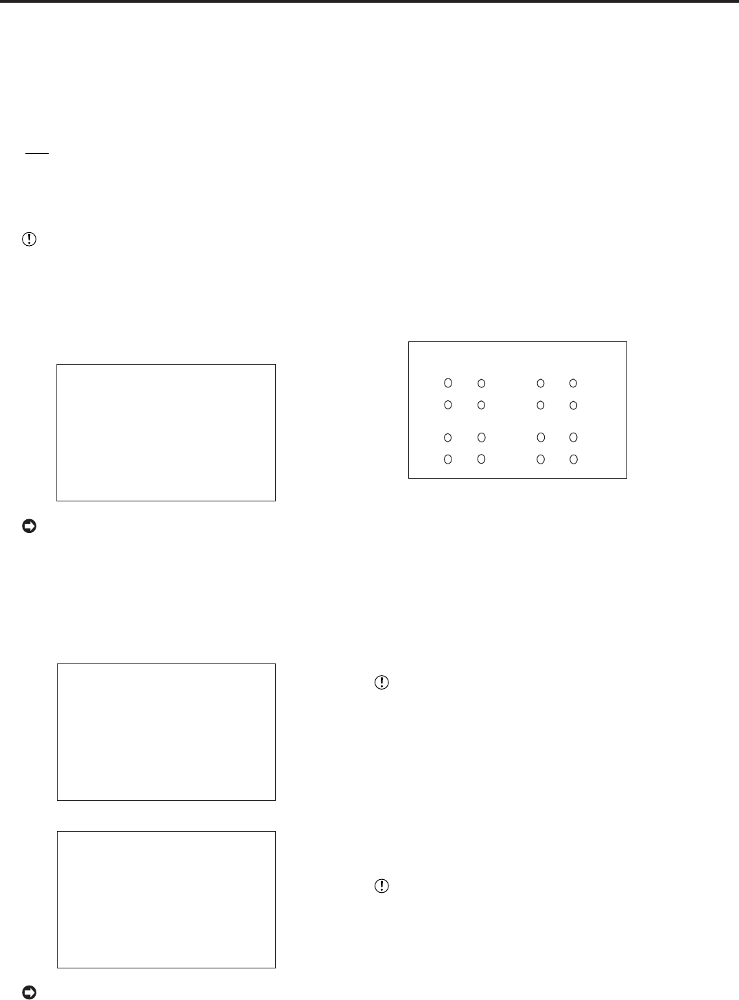
■ SPLIT4 SCREEN SETTING
For the SPLIT4 SCREEN SETTING, 4 types of SPLIT4
screen types (a, b, c and d) can be set.
1. Press the SET UP button
}
<SETTINGS>
}
Select
“OUTPUT A” (“OUTPUT B”) in the <MPX DISPLAY
SETTINGS> screen and turn the SHUTTLE ring clockwise.
• The <OUTPUT A> (<OUTPUT B>) screen appears.
2. Turn the JOG dial to select “SPLIT4 SCREEN SETTING”
and turn the SHUTTLE ring clockwise.
• The <SPLIT4 SCREEN SETTING> screen appears.
9
10
11
13
14
15
16
12
7
4
5
6
1
2
3
8
<SPLIT4 SCREEN SETTING>
>>
SPLIT4(a) SPLIT4(b)
( ) ( ) ( ) ( )
( ) ( ) ( ) ( )
SPLIT4(c) SPLIT4(
d
)
( ) ( ) ( ) ( )
( ) ( ) ( ) ( )
3. Turn the JOG dial to select the split display to set (a, b, c or
d) and turn the SHUTTLE ring clockwise.
• The (most upper left) camera number reverses in color.
4. Turn the JOG dial to move to the camera number with the
reversed display and turn the SHUTTLE ring clockwise.
• The background of the camera number turns red and
flashes.
5. Turn the JOG dial to display the camera number to set and
turn the SHUTTLE ring.
• Flashing stops.
The same camera number can be set multiple
times on the split screen display. When multiple set-
tings with the same camera number have been
made, the same image is displayed at the camera
location.
6. Repeat steps 4 and 5 to set the desired camera number.
7. When completed with setting, turn the SHUTTLE ring
counterclockwise.
• Setting is confirmed and the cursor appears.
8. To set other split screen displays, repeat steps 3 ~ 7.
The <SPLIT4 SCREEN SETTING> screen can-
not be exited when camera number is flashing.


