


PAGE 24 — MAYCO C-30HDG PUMP — OPERATION AND PARTS MANUAL — REV. #6 (04/02/12)
C-30HDG PUMP — CONTROL BOX COMPONENTS
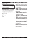
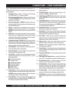
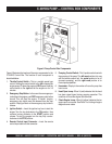
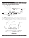
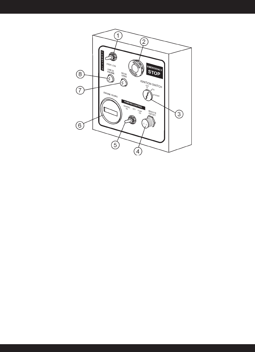
Figure 8. Pump Control Box Components
Figure 8 illustrates the location of the major components for the
C-30HDG Control Box. The function of each component is
described below:
1. Throttle Control Switch – This is a variable speed type
control. Holding the control switch to the
left
increases the
engine speed. To place the engine at IDLE speed, hold the
control switch to the
right
and let the engine run for 3-5
minutes.
2. Emergency Stop Button– In the event of an emergency or
to shutdown the engine, push RED emergency stop button
inward. This will stop the engine. To restart engine,
emergency stop button must be released from the stop
position. Simply pull back on the emergency stop button to
release.
3. Ignition Switch – Insert the ignition key here to start the
engine. Turn the key clockwise to the ON position, then
continue turning clockwise to the START position and
release. To stop the engine turn the key fully counter-
clockwise to the
STOP position.
4. Remote Control Input Connector – Insert the remote
control input cable into this connector.
5. Pumping Control Switch – This 3-position switch controls
the pumping of the pump. The
left most
position is for use
with the remote control unit, the
center
position is for off
(prevents pumping), and the
right most
position is for
normal pump operation.
6. Hourmeter– Display's the number of hours the pump has
been in use.
8. Hood Open Lamp– When lit (red) indicates that the hood
has been raised (open) during pumping operation. This
condition will force the engine into idle mode.
7. Check Engine Lamp– When lit (yellow) indicates that an
engine error as occured. See Table 7 for a listing of engine
diagnostic error codes.