


7
SET-UP
1. Uncrate mower, cut four plastic ties holding
mower to pallet.
2. Mount front caster assemblies to the front deck
using the fasteners provided on the deck (both
sides)
3. Cut the plastic wire ties holding the operator
presence levers down.
4. Check tire pressure in all four tires. (Rear tires
15 PSI, front tires 15 PSI)
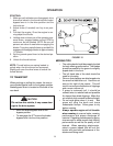
5. Check engine oil with dipstick. Add if needed
per engine manufactures specifications. (See
engine manual.)
EQUIPMENT:
CUTTING HEIGHT:
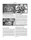
1. Before changing cutting heights make sure the
blades are off, key switch is off, and remove
spark plug wire or wires.
2. Cutting height ranges from 1 1/2” to 5” in 1/4”
increments. Factory setting is 3”.
3. Cutting height can be changed three ways.
Move one “C” spacer on the front casters,
change the blade spacers, or change rear deck
position.
4.
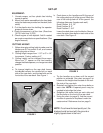
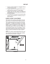
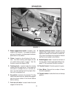
a. To change heights on the rear deck loosen,
but do not remove the middle bolt on each
side of the rear deck, and the two bolts on the
front side of the rear deck. See Figure 1.
NOTE: To achieve the best quality cut, the
blades should be level with the ground or
slightly tipped down in the front.
b. Push down on the handles and lift the rear of
the cutting deck up off of the ground. Block the
rear of the cutting deck off of the ground the
following distances (boards work well).
Deck Position A: 3 1/4”
Deck Position B: 2”
Deck Position C: 3/4”
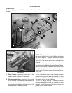
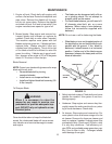
Lower the deck down onto the blocks. Now re-
move the outer three bolts on each side of the
rear deck. See Figure 2.
LOOSEN
FIGURE 1
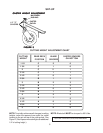
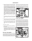
c. Tip the handles up or down until the correct
position is achieved. See chart on page 9 or
reference the height decal located on the muf-
fler side of the rear deck.
d. Reinstall and tighten the outer three bolts on
each side. NOTE: A tapered punch may be
needed to help align the holes.
e. Retighten the center bolts on each side and
the two bolts on the front of the rear deck.
5. Using the chart (on page 9), find the correct
number of spacers to be placed under the
caster swivel. Reference chart on page 9.
FIGURE 2
REMOVE